Combustible Dust Testing

Laboratory testing to quantify dust explosion and reactivity hazards

Safety Data Sheets

Develop critical safety data for inclusion in SDS documents

Gas and Vapor

Laboratory testing to quantify explosion hazards for vapor and gas mixtures

UN-DOT
Classification of hazardous materials subject to shipping and storage regulations
Hydrogen
Testing and consulting on the explosion risks associated with devices and processes which use or produce hydrogen
Safety Data Sheets

Develop critical safety data for inclusion in SDS documents

Thermal Stability

Safe storage or processing requires an understanding of the possible hazards associated with sensitivity to variations in temperature

Adiabatic Calorimetry
Data demonstrate the consequences of process upsets, such as failed equipment or improper procedures, and guide mitigation strategies including Emergency Relief System (ERS) design
Reaction Calorimetry
Data yield heat and gas removal requirements to control the desired process chemistry
Battery Safety

Testing to support safe design of batteries and electrical power backup facilities particularly to satisfy UL9540a ed.4

Safety Data Sheets

Develop critical safety data for inclusion in SDS documents

Cable Testing
Evaluate electrical cables to demonstrate reliability and identify defects or degradation
Equipment Qualification (EQ)
Testing and analysis to ensure that critical equipment will operate under adverse environmental conditions
Water Hammer
Analysis and testing to identify and prevent unwanted hydraulic pressure transients in process piping
Acoustic Vibration
Identify and eliminate potential sources of unwanted vibration in piping and structural systems
Gas & Air Intrusion
Analysis and testing to identify and prevent intrusion of gas or air in piping systems
ISO/IEC 17025:2017

Fauske & Associates fulfills the requirements of ISO/IEC 17025:2017 in the field of Testing

ISO 9001:2015
Fauske & Associates fulfills the requirements of ISO 9001:2015
Dust Hazards Analysis
Evaluate your process to identify combustible dust hazards and perform dust explosion testing
On-Site Risk Management
On-site safety studies can help identify explosibility and chemical reaction hazards so that appropriate testing, simulations, or calculations are identified to support safe scale up
DIERS Methodology
Design emergency pressure relief systems to mitigate the consequences of unwanted chemical reactivity and account for two-phase flow using the right tools and methods
Deflagrations (Dust/Vapor/Gas)

Properly size pressure relief vents to protect your processes from dust, vapor, and gas explosions

Effluent Handling

Pressure relief sizing is just the first step and it is critical to safely handle the effluent discharge from an overpressure event

FATE™ & Facility Modeling

FATE (Facility Flow, Aerosol, Thermal, and Explosion) is a flexible, fast-running code developed and maintained by Fauske and Associates under an ASME NQA-1 compliant QA program.

Mechanical, Piping, and Electrical
Engineering and testing to support safe plant operations and develop solutions to problems in heat transfer, fluid, flow, and electric power systems
Hydrogen Safety
Testing and consulting on the explosion risks associated with devices and processes which use or produce hydrogen
Thermal Hydraulics
Testing and analysis to ensure that critical equipment will operate under adverse environmental conditions
Nuclear Safety
Our Nuclear Services Group is recognized for comprehensive evaluations to help commercial nuclear power plants operate efficiently and stay compliant
Radioactive Waste
Safety analysis to underpin decomissioning process at facilities which have produced or used radioactive nuclear materials
Adiabatic Safety Calorimeters (ARSST and VSP2)

Low thermal inertial adiabatic calorimeters specially designed to provide directly scalable data that are critical to safe process design

Other Lab Equipment and Parts for the DSC/ARC/ARSST/VSP2 Calorimeters

Products and equipment for the process safety or process development laboratory

FERST

Software for emergency relief system design to ensure safe processing of reactive chemicals, including consideration of two-phase flow and runaway chemical reactions

FATE

Facility modeling software mechanistically tracks transport of heat, gasses, vapors, and aerosols for safety analysis of multi-room facilities

Blog

Our highly experienced team keeps you up-to-date on the latest process safety developments.

Process Safety Newsletter

Stay informed with our quarterly Process Safety Newsletters sharing topical articles and practical advice.

Resources

With over 40 years of industry expertise, we have a wealth of process safety knowledge to share.

Recent Posts

Determination of Two-Phase Flow Regimes and Pressure Relief Sizing

Posted by Fauske & Associates on 08.29.13

Dr. Hans Fauske, D.Sc., Regent Advisor, Fauske & Associates, LLC (FAI)

A first order evaluation of vessel two-phase flow regimes and their effect on pressure relief sizing can be reduced down to determining if the system in question exhibits foamy behavior. This is the case for both non-reactive as well as reactive systems and needs to be evaluated under conditions coinciding with the relief venting process and pressure.

In contrast to the often debated depressurization technique, a simple method to determine the prevailing regime characteristic at both low (near atmospheric) and higher pressure relief conditions is the ARSST flow regime detector illustrated in Figure 1 (Fauske, 2000).

Figure 1

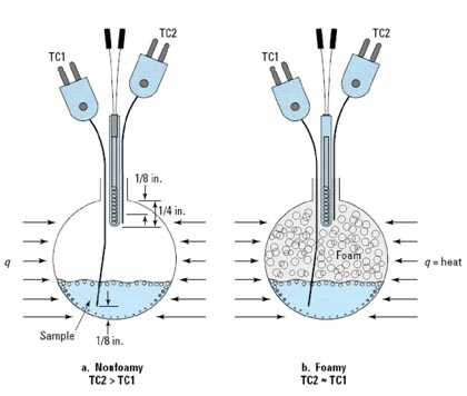
Figure 1: Illustration of Non-foamy and Foamy Behavior

The importance of flow regime characterization and pressure relief sizing is illustrated in Figure 3 in case of fire exposure and is relevant to storage vessels including both non-reactive and reactive conditions (Fauske, 2006).


Figure 3a illustrates all vapor venting in case of non-foamy behavior, while Figure 3b illustrates two-phase venting in case of foamy behavior, where the void fraction entering the relief device is of the order of 0.99. Despite the high void fraction foam entering the vent line, the required vent area is several times the area required for the non-foamy behavior, all other conditions remaining the same.

Figure 2
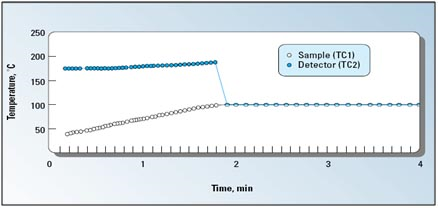
Figure 2: Illustrating Foamy Behavior

The detector employs a small immersion heater and an attached thermocouple (TC2) that is positioned in the upper freeboard space of the test cell. The TC2 temperature should be well above the anticipated temperature of the sample (TC1). The detector operates on the simple principle that if the flow regime following onset of boiling or decomposition is foamy, then the detector will be wetted and rapidly cooled as illustrated in Figure 2. If the flow regime is non-foamy, then the detector thermocouple TC2 will continue to measure a temperature well in excess of the sample temperature TC1.

Figure 3
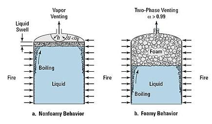
Figure 3: Illustrating Non-foamy and Foamy Behavior in Case of Fire Exposure

A further illustration of the importance of flow regime characterization and pressure relief sizing is illustrated in Figure 4 for process vessels and is relevant to reactive vapor systems (tempered reactions).

Figure 4a illustrates two-phase venting characterized by the churn turbulent flow regime in case of non-foamy behavior, while Figure 4b illustrates two-phase venting characterized by the bubbly flow regime in case of foamy behavior. In case of a nearly liquid-full process vessel, the vent area requirement for the foamy case is about twice that required for the non-foamy case, all other conditions remaining the same (Fauske, 2006). It also follows that the required liquid fill fraction to prevent two-phase flow can be much higher for the non-foamy case than the foamy case.

Figure 4
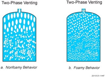
Figure 4: Illustrating Non-foamy and Foamy Behavior in Case of Process Vessels

Finally, for gassy decomposition systems (non-tempered reactions) experience indicates that for foamy behavior the vent area can be based upon all gas venting at peak reaction condition and no reactant loss (Fauske, 2006). In case of non-foamy behavior the vent area again can be based upon all gas venting at peak reactive conditions with potential reactant mass loss determined by the churn turbulent flow regime (Fauske, 2006) resulting in a smaller vent area, all other conditions remaining the same.

References

Hans K. Fauske, 2000, “Properly Size Vents for Nonreactive and Reactive Chemicals,” Chemical Engineering Progress, February 2000.

Hans K. Fauske, 2006, “Revisiting DIERS’ Two-Phase Methodology for Reactive Systems Twenty Years Later,” Process Safety Progress, Vol. 25, No. 3, September 2006.

For more information, please contact 1-877-FAUSKE-1 or afauske@fauske.com

Hazard Identification And Analysis For  Reactive Chemical Systems


Topics: ARSST, Reactive Chemicals, Testing

cta-bg.jpg

Is My Dust Combustible?

A Flowchart To Help You Decide
Download Now