MAAP5 Analysis of Various Injection Strategies during Extended Loss of AC Power
Fauske & Associates, LLC (FAI) is deeply involved in the analysis of severe accidents and the development of severe accident computational models. FAI uses the Modular Accident Analysis Program (MAAP) software that is owned and licensed by the Electric Power Research Institute (EPRI). MAAP is utilized by nuclear utilities worldwide to analyze abnormal plant transients and severe accidents, such as station blackouts (SBO) or loss of coolant accidents (LOCA), and to guide development of severe accident management guidelines (SAMGs). Severe accident management consists of mitigation actions before and after core damage has occurred.
During shutdown conditions, the severe accident progression is not very sensitive to the initial water level in the vessel except with regard to the time of core uncovery and core damage. However, the thermal hydraulic conditions in the primary system, steam generators, and containment can affect the SAMG actions and progression of the accident. If mobile equipment is unavailable for an extended loss of AC power (ELAP) during shutdown conditions with an open RCS (pressurizer or steam generator manways are open), establishment of gravity injection from the refueling water storage tank (RWST) or condensate storage tank (CST) into the RCS can be an important operator action.
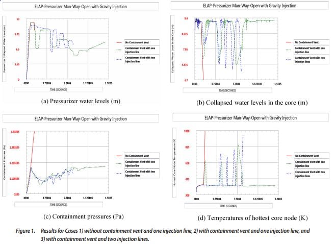
An example analysis of gravity injection during an extended loss of AC power (ELAP) is shown for how MAAP5 was used for shutdown SAMG development. Three sample MAAP runs were performed for a typical Westinghouse type four loop plant:
- One 5” gravity injection line without any containment heat removal and without containment vent
- One 5” gravity injection line with containment vent (8” vent line opened at 1.22 bar (3 psig) and left open)
- Two 5” gravity injection lines with containment vent
The runs were stopped when the core exit temperature exceeded 1200 °F. An analysis of the results is provided in the following paragraph.
After the loss of residual heat removal (RHR) cooling, the core temperature reaches the saturation temperature soon and boiling occurs in the core. The boiling in the core pushes two-phase water into the hot leg and the pressurizer. As a result, the water level in the pressurizer increases as shown in Figure 1(a). Without the containment vent, the gravity injection soon stops because of the high containment pressure and high water level in the pressurizer. With the containment vent available, the high pressurizer level and up to 3 psig of containment back pressure shuts off the gravity injection from time to time resulting in core uncovery in both cases with one and two injection lines. Figure 1(b) shows the mixture water level in the core. When the injection flow stops, the core was uncovered and the mixture level decreases enough to reduce the steaming rate and the two-phase carry-over to the pressurizer.
In most conditions, the pressurizer surge line is flooded and water drainage from the pressurizer to the hot leg is prevented. However, the pressurizer level decreases from time to time due to counter-current water drainage when the core is uncovered. Figure 1(c) shows the containment pressure. Without the containment vent, high containment pressure prevents gravity injection. For the other two cases, an 8” containment vent line was opened at 3 psig and remained open throughout the remainder of the sequence. Figure 1(d) shows the hottest core node temperature. The number of lines used for gravity injection makes some difference in the pressurizer water level and timing of core uncovery. However, the general responses between two cases are similar. For the case with two injection lines, the run is stopped because the core exit temperature exceeded 1200 F.
The success of gravity injection during an ELAP with the pressurizer manway open depends on several plant specific factors:
- Elevation difference between the RWST and RCS and the water level in the RWST
- Availability of external RWST makeup
- Containment vent (or containment heat removal) available or not
- Number of injection lines, size, and the discharge coefficient of the piping
- Decay heat

In the samples above, MAAP5 was used to predict the primary system and containment response to gravity injection during an ELAP with and without containment venting and at various injection flow rates. Analysis can also be done to determine timings of events such as timing of core uncovery and time to vent the containment for various scenarios such as:
- Accidents initiated during shutdown conditions when the RCS is closed and SG injection is available to 1 steam
generator - Gravity injection from the RWST during an ELAP (as demonstrated here)
- External injection using a fire pump for a case when the gravity injection has failed, and more
The insights from plant specific MAAP5 calculations similar to the sample calculations can be used to guide SAMG development.
