Introduction
Electric cables are essential to all industrial processes. They serve several functions, including power transmission and supply, instrumentation and control. Despite their importance, cables typically receive little attention — they are considered passive, enduring components that are very reliable. In reality, like most other components, cables are susceptible to degradation. Cable aging may lead to increased electrical noise, worsened electrical properties, and eventually cable failures. Cable failures have caused safety concerns, resulted in accidents, lost revenue, and even lead to power loss and plant shutdowns.
In general, cables are often composed and specified by three key parameters: the conductor, insulation, and jacket. The primary component of concern in regards to cable degradation is the insulation material around the metallic conductor. The insulation is protected by the jacket (or outer material) of the cable. Additionally, depending on the voltage and application, cable construction can also include other components such as shields and semiconductor tape.
Cable reliability is a growing concern in industry, and is both economic and regulatory driven. Cable related requirements have resulted from a fairly recent shift in regulatory compliance. Specifically, there are new cable related requirements for nuclear power plant life extensions where aging has become a factor for cables in safety-critical applications. This issue is discussed in the Nuclear Regulatory Commission (NRC) report Generic Aging Lessons Learned (NUREG 1801). Cable aging continues to be an important research topic for the NRC and EPRI. A key question for cable users regarding cable reliability is how can we evaluate cable health based upon non-destructive field measurements?
There are several test methods available to evaluate cable performance. Some methods stress the cable beyond their normal operating conditions — sometimes to failure. Other methods provide an indication of the overall performance of the cable, but do not identify localized damage. Most testing methods also require the cables under test to be de-terminated.
The LIne Resonance Analysis (LIRA®) cable condition monitoring test overcomes these obstacles and provides both an indication of the overall cable health as well as locally degraded areas. LIRA is a nondestructive evaluation tool that does not over-stress the cable; it uses a low 5 volt DC peak-to-peak (Vpp) signal to perform its’ evaluation. Unlike most traditionally used testing techniques, LIRA performs both global and local assessments of the test cable. Additionally, the test cable does not need to be disconnected from its source to perform LIRA testing and the test is completed in minutes. Leaving the cable connected eliminates a step that could result in issues with cable performance after the test during normal operation: the cable termination or re-termination.
How Does LIRA Work?
LIRA is based on transmission line theory. A transmission line can be viewed as any two conductors with an applied voltage. A common type of transmission line is overhead cables lining many streets which transmit power from a generator to various loads. Another type of transmission line is a coaxial cable or two strips on a printed circuit board.
LIRA transmits a variable frequency wave (signal) and calculates the line impedance as a function of the frequency; this technology is commonly referred to as frequency domain reflectometry or FDR. As the transmitted signal encounters changes in impedance resulting from changes in the type of cable insulation, splices, degraded insulation, or other, a reflected signal is returned to LIRA. The magnitude of the reflected signal determines the relative severity of the identified impedance change(s) while the phase angle of the reflected signal corresponds to the location of the identified impedance change(s). Combined, these two measurements characterize the localized impedance change.
The identified localized impedance changes can be normal (i.e., well installed splices) or not. Abnormal impedance changes are due to certain cable stressors. Cable stressors include: higher than normal thermal conditions, mechanical damage, water/humidity, chemical interactions, and radiation among others. An assessment of the identified impedance change can then be performed to determine what, if any actions are required. For example, The test results may indicate that local cable repairs are warranted rather than requiring complete cable replacement.
In addition to localized insulation damage, LIRA also provides an overall assessment of the cable’s global condition by an established LIRA Health Index (LHI). With this information, a, assessment of the condition of the cable under test can be established.
Lira Testing Setup
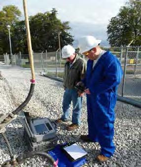
Testing a cable with LIRA is quick and simple. The only requirement for operation is for the cable to be deenergized. The cable does not need to be de-coupled or de-terminated. For example, a breaker can be opened and the test leads connected to the stabs. Then the two LIRA test leads are connected to two metal cores of the cable (for example, two conductors or one conductor and a shield) using alligator clips, a coaxial cable connector or similar devices. Depending on the length of the test cable, a typical LIRA test will take about three minutes.
Example LIRA Testing Results
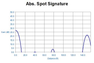
The following is an example of LIRA testing results. These test results are from a short (150 ft) low voltage twisted pair cable system with thermal damage to the cable insulation at 78 feet. This damage location is clearly seen when observing the LIRA Signature Plot, as shown in the following graph.

The LIRA Signature plot is a normalized trend that shows LIRA signal strength (labeled as “Gain (dB)”) as a function of the length of the cable (labeled as “Distance (ft)”). For LIRA, it is typical to have a signal peak at the start of a cable and a similar peak at the end of the cable. The peak at 78 feet represents the location of the thermal damage. This relationship is used to determine areas of potential impedance related performance issues based upon the magnitude of the peak. The X-axis is used to identify the location of the area of interest using the X-axis scale, where 0 is the location of where the LIRA test unit was attached to the cable under test.
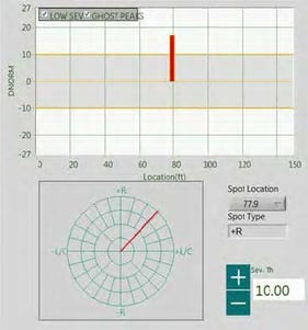
Insight into the cause of the impedance change can be found in the DNORM relationship. The following is the DNORM plot for the example LIRA test case.
 The LIRA DNORM plot compliments the LIRA Signature plot by providing additional information about identified impedance changes along the cable. The DNORM plot provides a normalized graphical interpretation of the finding along the measured cables length, without the start and end terminations shown. The direction of the severity can be used to further determine the cause in some cases. A negative impedance variation, for example, could mean water ingression in cables exposed to water environments and positive impedance could be due to mechanical or thermal damage.
To determine the health of the cable under test, the LIRA Health Index (LHI) is used. LHI provides a classification of the Health of the cable and actions:
1) Green (good) – No actions required
2) Yellow (caution) - Further study advised
3) Red (warning) - Action required
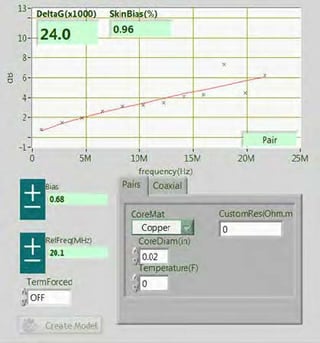
A key indicator of the LIRA Health Index (LHI) is the LIRA Delta-G (LDG) parameter. The following graph is the LDG for the example test cable discussed above.
 Based upon the type of insulation of the cable for this example, a a LDG value of 24 x 10-3 corresponds to a cable health of “Yellow” and a classification of “Further study required”. It should be noted that the LHI is currently under development.
For more information or to discuss further, please email us at info@fauske.com, (630) 323-8750. www.Fauske.com
#cable testing

