Combustible Dust Testing

Laboratory testing to quantify dust explosion and reactivity hazards

Safety Data Sheets

Develop critical safety data for inclusion in SDS documents

Gas and Vapor

Laboratory testing to quantify explosion hazards for vapor and gas mixtures

UN-DOT
Classification of hazardous materials subject to shipping and storage regulations
Hydrogen
Testing and consulting on the explosion risks associated with devices and processes which use or produce hydrogen
Safety Data Sheets

Develop critical safety data for inclusion in SDS documents

Thermal Stability

Safe storage or processing requires an understanding of the possible hazards associated with sensitivity to variations in temperature

Adiabatic Calorimetry
Data demonstrate the consequences of process upsets, such as failed equipment or improper procedures, and guide mitigation strategies including Emergency Relief System (ERS) design
Reaction Calorimetry
Data yield heat and gas removal requirements to control the desired process chemistry
Battery Safety

Testing to support safe design of batteries and electrical power backup facilities particularly to satisfy UL9540a ed.4

Safety Data Sheets

Develop critical safety data for inclusion in SDS documents

Cable Testing
Evaluate electrical cables to demonstrate reliability and identify defects or degradation
Equipment Qualification (EQ)
Testing and analysis to ensure that critical equipment will operate under adverse environmental conditions
Water Hammer
Analysis and testing to identify and prevent unwanted hydraulic pressure transients in process piping
Acoustic Vibration
Identify and eliminate potential sources of unwanted vibration in piping and structural systems
Gas & Air Intrusion
Analysis and testing to identify and prevent intrusion of gas or air in piping systems
ISO/IEC 17025:2017

Fauske & Associates fulfills the requirements of ISO/IEC 17025:2017 in the field of Testing

ISO 9001:2015
Fauske & Associates fulfills the requirements of ISO 9001:2015
Dust Hazards Analysis
Evaluate your process to identify combustible dust hazards and perform dust explosion testing
On-Site Risk Management
On-site safety studies can help identify explosibility and chemical reaction hazards so that appropriate testing, simulations, or calculations are identified to support safe scale up
DIERS Methodology
Design emergency pressure relief systems to mitigate the consequences of unwanted chemical reactivity and account for two-phase flow using the right tools and methods
Deflagrations (Dust/Vapor/Gas)

Properly size pressure relief vents to protect your processes from dust, vapor, and gas explosions

Effluent Handling

Pressure relief sizing is just the first step and it is critical to safely handle the effluent discharge from an overpressure event

FATE™ & Facility Modeling

FATE (Facility Flow, Aerosol, Thermal, and Explosion) is a flexible, fast-running code developed and maintained by Fauske and Associates under an ASME NQA-1 compliant QA program.

Mechanical, Piping, and Electrical
Engineering and testing to support safe plant operations and develop solutions to problems in heat transfer, fluid, flow, and electric power systems
Hydrogen Safety
Testing and consulting on the explosion risks associated with devices and processes which use or produce hydrogen
Thermal Hydraulics
Testing and analysis to ensure that critical equipment will operate under adverse environmental conditions
Nuclear Safety
Our Nuclear Services Group is recognized for comprehensive evaluations to help commercial nuclear power plants operate efficiently and stay compliant
Radioactive Waste
Safety analysis to underpin decomissioning process at facilities which have produced or used radioactive nuclear materials
Adiabatic Safety Calorimeters (ARSST and VSP2)

Low thermal inertial adiabatic calorimeters specially designed to provide directly scalable data that are critical to safe process design

Other Lab Equipment and Parts for the DSC/ARC/ARSST/VSP2 Calorimeters

Products and equipment for the process safety or process development laboratory

FERST

Software for emergency relief system design to ensure safe processing of reactive chemicals, including consideration of two-phase flow and runaway chemical reactions

FATE

Facility modeling software mechanistically tracks transport of heat, gasses, vapors, and aerosols for safety analysis of multi-room facilities

Blog

Our highly experienced team keeps you up-to-date on the latest process safety developments.

Process Safety Newsletter

Stay informed with our quarterly Process Safety Newsletters sharing topical articles and practical advice.

Resources

With over 40 years of industry expertise, we have a wealth of process safety knowledge to share.

Recent Posts

Revisiting Mitigation Options for Acoustic Resonances in Pipe Attachments

Posted by Fauske & Associates on 10.03.17

By Jens Conzen, Director of Plant Services, Fauske & Associates, LLC

Typical power and process plant systems will always vibrate under operation to some degree. This is due to various reasons such as turbulence, acoustics, or excitation from rotating equipment, for example. Acoustic resonance in piping systems can be caused if dead ended side branches, stand pipes, or drip legs are being excited. The flow across the throat of the attachment can produce a vortex shed on the leading edge of the entrance that occurs at a constant frequency. If that frequency is close to the quarter wave length frequency of the branch, an acoustic resonance can occur as exemplified in the graphic below:
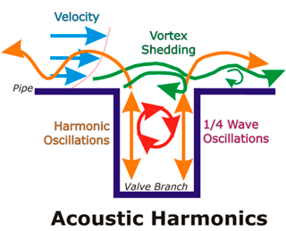
Acoustic Harmonics

In this case, one would refer to the event as flow-induced vibration. The natural frequencies for the various geometries can be estimated by using simple algebraic formulations. The frequency of vortex shedding can be estimated by following the guidance of Ziada and Shine [1]. If vibration data taken with accelerometers and strain gauges suggest an acoustic resonance at unacceptable levels (see also FAI N-16-13), and it is also confirmed by acoustic screening calculations, actions must be taken for mitigation.

A variety of options (operational and hardware changes) exist that can help mitigating the vibration amplitude for side branch excitation.

Plant Operation:
For partial load operation, it might be possible to close one process line and consequently increase the flow velocity in the remaining lines. This could decouple the excitation source. However, this should be carefully verified by analysis and testing.

Plant Modification:
The main options for pipe line modifications are: 1) a vesselet configuration to decouple the vortex shedding frequency from the cavities, 2) an acoustic side branch to add damping and disturbance, or 3) an open bypass connection to add disturbances. Schematics for these options are shown below.
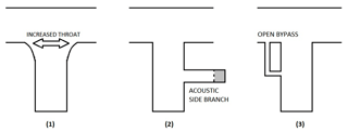
Pipeline Modifications sketch


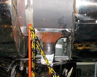
A vesselet inlet configuration increases the throat width which causes the frequency of the vortex shed to change. In addition, the edges of the inlet to the drain stub are rounded with a fairly large radius compared to a sharp edge. This measure makes it more difficult for a distinct vortex shed to establish at the leading edge. A vesselet configuration would most likely decouple the excitation from the cavity. Vesselet branch connections have been used in industry application (see photo below).

An acoustic side branch (ASB) may be installed to mitigate the resonance phenomenon. This concept has also been proven successful in the industry. The ASB changes the frequency of the attachment and it contains a material that dampens the acoustic pressure. The acoustic pressure loading may not be eliminated with an ABS, but appreciable reductions in amplitude and shift in frequencies have been observed.

An open bypass adds disturbance to the cavity that could disrupt and lift the quarter wave. This has been tested for drip legs; opening of the drain valve at the bottom of the drip leg eliminates the vibration. The flow through the bypass “stirs” the cavity, which makes it difficult for a quarter wave to develop. However, this solution is only effective if there is continuous flow through the bypass. This can only be achieved by adding resistance into the main line.

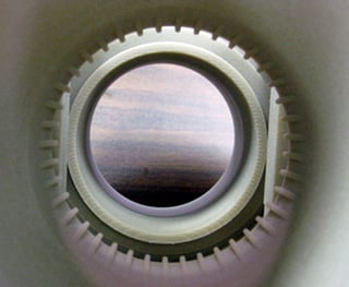
Other potential solutions may include changing the length of the attachments or by adding a spoiler just upstream on the leading edge of the tee connection (see photo below).

In any case, it is recommended to stringently verify potential modifications by analysis and testing prior to implementation. It is also recommended to try reversible modifications first, so that they can be removed, in case they
show unsatisfactory results.
 

                  Ref Pic 1a            Ref Pic 1b

References

“Ziada, S., Department of Mechanical Engineering, McMaster University Hamilton, Ontario, Canada, Shine, S., Department of Mechanical Engineering, University of Nairobi, Kenya, 1997, ”Strouhal Numbers of Flow-Excited Acoustic Resonance of Closed Side Branches”. Journal of Fluids and Structures, 1999, 127-142. Article No: jfls. 1988-0189.

For more information or discussion, contact us at info@fauske.com . www.fauske.com

#pipe vibration #power plant # plant safety

FAI Process Safety Newsletter

Topics: Nuclear

cta-bg.jpg

Is My Dust Combustible?

A Flowchart To Help You Decide
DOWNLOAD NOW