
When designing a safe process, our goal is to reduce risk by implementing layers of safeguards. One example of a risk in processing is a loss of containment, and a potential cause of this is an unexpected buildup of pressure. Emergency relief systems (ERS) are a safeguard used to mitigate overpressure scenarios to protect people, the environment, and infrastructure. If these systems are not adequately sized, installed, or maintained, catastrophic incidents can occur.
 We typically categorize potential sources of overpressure as either reactive or nonreactive, and it is important to note that reactive hazards can be present whether the reaction is intended or not, and there can be multiple sources of overpressure present for a given piece of equipment or process. Examples of hazards that could lead to overpressure include fire exposure, loss of power or cooling, and overcharge or undercharge of reactant, catalyst, or solvent.
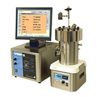
Evaluating or designing an ERS requires careful consideration of the upset scenario(s) that lead to an overpressurization (hazard characterization), the rate at which this pressure builds in the system (source of pressurization), and the rate at which pressure can be relieved from the system (discharge rate). The upset scenario is typically determined during a systematic procedure such as a Process Hazard Analysis (PHA). A special subset of a PHA is a Reactive Hazard Assessment (RHA) in which potential reactive hazards are identified within a process. Once potential hazards are identified, the hazard can be evaluated, and the source rates can be obtained using a low phi-factor adiabatic calorimeter like the VSP2 [1] pictured in Figure 1.
Additionally, an ERS design is dependent on both the vessel and relief device details. The discharge rates depend on the flow regime and material properties of the fluid. The focus of this discussion, is the selection and impact of material properties in the context of ERS design. This is not only important for appropriately protecting the vessel against overpressurization, but there are also downstream effluent considerations that are impacted by material properties.
Vent Sizing Basics
In relation to vent sizing evaluations, the source of pressurization is often modeled using three general classifications: a tempered (or vapor system), a non-tempered (or gassy system), and a gas generating tempered system (hybrid system).
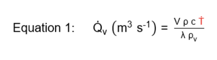
Vapor systems describe both reactive and nonreactive situations where pressure generation is due to an increase in the vapor pressure of a liquid. In this system, evaporation of the liquid is used to control or “temper” the exothermic reaction. The required volumetric vapor generation rate which the ERS must accommodate to ensure that the vessel of interest is not over pressurized is related to the temperature rise rate as described in Equation 1.
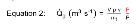
Gassy systems describe a situation where non-condensable gas generation , for example oxygen or carbon dioxide reaction products, is the cause of the pressure buildup. In this system, the latent heat of vaporization is not available for tempering, and the reaction temperature cannot be controlled by venting. Therefore, the source term is a function of pressure rise rate alone. The volumetric gas generation term is described in Equation 2.
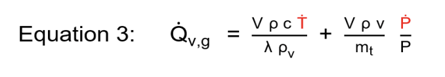
Finally, hybrid systems describe situations where both vapor and gas generation coincide in the venting region . The latent heat of cooling is available at the relief pressure, and the reaction temperature can be controlled by venting, but noncondensable gas is also occurring simultaneously. The hybrid (summation of vapor and gas) generation term is described in Equation 3.
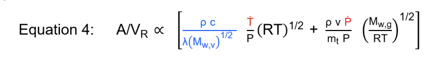
Below is a simplified version of a vent sizing equation where we see the ideal vent area is proportional to these two terms depending on the system type. The blue term in Equation 4, highlights the lumped material properties that are required to represent vapor generation. We need to know the liquid density ρ, liquid heat capacity c, latent heat of vaporization λ, and the molecular weight of the vapor Mw,v corresponding to the temperatures and pressures of relief. This article will further explore the impact of this lumped parameter on the ideal vent size.
Material Properties for ERS Design
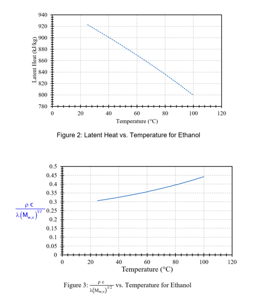
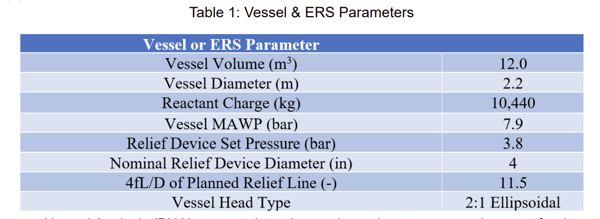
Material properties are composition and temperature dependent, and when evaluating or designing an ERS, we are specifically interested in the properties of the vented fluid at our elevated relieving conditions. Figures 2 and 3 provide the latent heat of vaporization and lumped parameter term highlighted in blue from Equation 4 for ethanol as a function of temperature [2] and provide an example of the temperature dependence of material properties crucial for ERS design.
Ideally, pure component or mixture properties of the anticipated relieving fluid can be found in literature such as the NIST Webbook [3], DIPPR [2], or within the material SDS. Alternatively, there are tools for experimentally measuring material properties such as utilizing the VSP2 to measure the vapor pressure of the material to extract the latent heat of vaporization. Unfortunately, it can be difficult to find properties in the literature, and sometimes experimentally measuring these properties is not feasible. Therefore, we have adopted a staged approach to selecting material properties for ERS evaluations and design:
- Use a Single (Dominating or Similar) Component to Represent a Mixture
- Assume Ideal Mixing Properties
- Employ Thermodynamic Mixing Models
Case Study — Repurposing an Existing Vessel
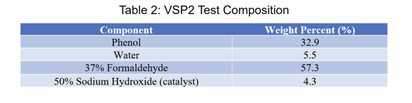
This example explores repurposing an existing vessel. Two potential uses have been identified: a reactor for a phenol-formaldehyde process, or a storage vessel for an ethanol, water, and propylene glycol mixture. The vessel is internally agitated, and the vessel and relief device parameters are listed in Table 1.
A Process Hazard Analysis (PHA) was conducted to evaluate the two prospective uses for the vessel. The PHA identified that both a fire exposure scenario as well as a loss of cooling scenario during the reaction are possible sources of overpressure for the phenol-formaldehyde process. There are two potential methods for running the reaction: batch or semi-batch depending on the final product use, and therefore, both methods must be evaluated for the loss of cooling scenario. For use as a storage tank, fire exposure was identified as the only credible upset scenario.
Phenol Formaldehyde Reactor ERS Design
To evaluate the adequacy of the vessel as a reactor and potential relief line to protect the reactor from overpressurization, we start by evaluating the ideal vent diameter needed for each identified upset scenario. The PHA found that for the fire exposure scenario, a fire was most likely to occur when the vessel contents were nonreactive. Therefore, when evaluating the adequacy of the existing relief system to protect the reactor during a fire exposure scenario, nonreactive venting is considered with the source term based on API 521 (found to be 651 kW without insulation but considering prompt fire-fighting and adequate drainage) [4].
For the loss of cooling scenarios, adiabatic calorimetry was performed simulating both the batch and semi batch processes. A summary of the approximate tested composition for each experiment is shown in Table 2.
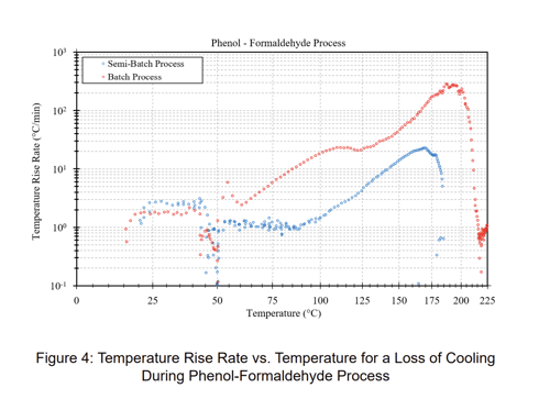
The data indicate that vapor generation will be the sole source of overpressure in the venting region. The temperature rise rate vs. temperature results from the VSP2 experiment are illustrated in Figure 4. Here the data representing the batch process are shown red, and the data representing the semi batch process (controlled addition of catalyst) are in blue. The flow regime for each scenario is assumed to be bubbly.
Six ideal vent sizing evaluations were conducted using the Leung Omega methodology [5-7] within FERST powered by CHEMCAD [8] assuming a bubbly flow regime; these are summarized in Table 3. The first three results use the best estimate material properties. For the fire exposure scenario (non-reactive vapor venting), water is the primary component expected to be present, and therefore it is assumed that the material properties of water adequately represent the relieving fluid. For the loss of cooling scenarios, ideal mixing (Raoult’s Law) material properties are employed, and this assumption was confirmed by comparing the measured vapor pressure to the predicted vapor pressure. For comparison, the blue lumped material property term (as shown in Equation 4) is doubled for the last three results.
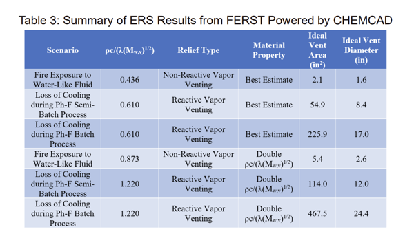
When comparing the results utilizing the best estimate material properties, we notice that the non-reactive vapor venting scenario results in an ideal vent area close to 30 times smaller than the semi-batch process results, and close to a factor of 100 times smaller than the batch process. Further, we notice that increasing the lumped material property term by a factor of two roughly doubles the ideal vent area.
These results illustrate the importance of first understanding and quantifying the worst plausible upset scenario and the source of pressurization associated with this scenario. It is crucial to identify and characterize this value because the source of pressurization can cause a step change of multiple orders of magnitude in the required vent area. Once the worst plausible upset scenario has been fully understood, and if further refinement in the required ideal area is justified, the material properties should be investigated further as the material properties can also have a direct impact on required ideal area.
Comparing only the results with the best estimate for the material properties, the scenario that results in the largest relief requirement is a loss of cooling during a batch process. The ideal vent diameter is 17” which is much greater than the available 4” vent diameter, and therefore this vessel is not adequately equipped to act as a reactor for the phenol-formaldehyde process.
Ethanol-Water-Propylene Glycol Storage Tank ERS Design
To evaluate the adequacy of the existing vessel for use as a storage tank for a complex mixture of ethanol-water-propylene glycol, a set of important questions must be answered:
- Is the mixture reactive or non-reactive?
- How much liquid is entrained during venting?
- How important are mixture material property calculations?
Stay-tuned for Part 2 to explore these questions and determine the adequacy of the existing vessel to act as a storage tank for the ethanol-water-propylene glycol mixture.
Conclusion
In summary, Part 1 of this article showcases the direct impact material property selection has on the relative size of an ERS design, but also clearly indicates that the detection and quantification of chemical reactivity often has the greatest impact on the ERS design. Part 2 of this article will further explore the effect vapor/liquid disengagement characteristics have on ERS design and provide an example of our recommended approach when pure component or ideal mixing material properties may not appropriately represent a relieving fluid.
The VSP2 is an excellent laboratory tool used to detect chemical reactivity (intended or not), and it measures directly scalable temperature and pressure rise rate source terms for ERS design. FERST Powered by CHEMCAD is an easy-to-use software tool to quickly apply VSP2 data to full-scale vessels with material properties for over 3,000 components built-in and with ~40 different thermodynamic mixing models available to represent a wide range of mixtures. Please contact eraines@fauske.com to learn more.
References
1. Fauske & Associates, Vent Sizing Package 2 (VSP2): https://www.fauske.com/blog/the-vsp2-still-relevant-to-processsafety-testing
2. The DIPPR Information and Data Evaluation Manager for the Design Institute for Physical Properties, Version 11.3.0, Database Date 2016, Brigham Young University
3. NIST Chemistry Webbook: https://webbook.nist.gov/
4. API Standard 521, “Pressure-relieving and Depressuring Systems,” American Petroleum Institute, Washington, D.C., Seventh Edition, June 2020
5. Leung, J. C., “Flashing Two-Phase Flow Including the Effects of Noncondensable Gases,” Journal of Heat Transfer, pp. 269-272 (February, 1991)
6. Leung, J.C., “Vent Sizing for Gassy and Hybrid Systems,” Safety of Chemical Batch Reactors and Storage Tanks, 1991
7. Leung, J.C. and Epstein, M.A., “A Generalized Correlation for Two-Phase Nonflashing Homogeneous Choked Flow,” Transactions of the ASME, Vol. 112, 1990
8. FERST powered by CHEMCAD Version 1.0.0.15653 Fauske & Associates, 2020