Timothy L. Cullina, P.E.*, Ashok G. Dastidar, M.B.A, Ph.D.
Abstract
The National Fire Protection Association (NFPA) issues codes to provide guidance for fire and explosion protection. Guidelines for combustible dust in wood pellet manufacturing facilities are covered by NPFA 664, Standard for the Prevention of Fires and Explosions in Wood Processing and Woodworking Facilities. In this case study, the first step was to review the process and determine which materials posed a combustible dust hazard. The next step was to evaluate the existing equipment according to the prescriptive requirements of NFPA 664. In some cases, the prescriptive requirements of NFPA 664 would require significant and expensive changes to the process. By performing a Process Hazards Analysis (PHA) on the wood pellet manufacturing process at this facility, a risk-based approach was applied to achieve an acceptable level of risk by implementing protective systems and safeguards.
Introduction
This case study began after a fire and combustible dust explosion occurred at a wood pellet manufacturing plant. This paper will describe the incident followed by the risk-based approach to address the combustible dust hazards at this facility. This approach consisted of three parts: a sampling plan for obtaining appropriate test data, a gap analysis, and a process hazard analysis.
Incident Description
A smoldering nest started in the pellet cooler and the local fire department was notified. As fire fighters prepared to extinguish the pellet cooler fire, a hot ember travelled through the ducting to the pellet cooler bag house and initiated a combustible dust deflagration. The deflagration ruptured the bag house explosion vent, resulting in a fire that propagated through the 6 foot duct through the wall and onto the side of a nearby corrugated steel silo located 8 feet away from the building. The flames spread up the side of the silo containing dried-wood particulate and through vents on the underside of its cone-shaped roof, causing hot embers to enter the silo and start another fire.
Figure 1 shows the relationship of the Pellet Cooler to its Bag House, and the Bag House to the Outside Silos. Figure 2 shows the explosion vent discharge openings and the silos. Figure 3 shows the Pellet Cooler Bag House after repairs. Scorch marks from the explosion are visible above the Bag House.
 |
 |
 |
|
Figure 1. Diagram of incident area |
Figure 2. Vent exits near outside silos |
Figure 3. Repaired pellet cooler bag house |
This same deflagration also blew off the bag house door and caused the isolation valve to close. The pressure held back by the closed isolation valve caused the ducting to rupture and spread fire all the way back to the bag house. Although the isolation valve located in the Hammer Mill Building and its attached ducting fell to the floor, the isolation valve prevented the deflagration from travelling to up-stream production equipment. No new fires started here.
The firefighters quickly quenched the initial Pellet Cooler fire and then spent the next 12 hours extinguishing the fire in the silo. During this time OSHA arrived to initiate their investigation.
No injuries occurred during this event and the body of the Bag House, now doorless, ductless, and ventless, remained otherwise intact. The Pellet Cooler sustained no damage and fire fighters even saved the silo. Within a week operations resumed.
Hazard Identification: Material Properties and Process Description
This plant receives both green and kiln-dried (KD) wood particulate that it handles separately until storage prior to pellet making. Figure 4 provides a process flow diagram of the pellet making process and identifies both green and KD wood particulate sampling points identified in the sampling plan.
Green wood, primarily large wood chips with smaller chips and sawdust, has moisture content near 50%. This material is reduced in size, dried and then reduced in size again. Then, roughly 85% of the wood particulate is conveyed into a storage silo in preparation for pellet making. The remaining 15% of the green wood particulate is fed through a third, smaller hammer mill for further size-reduction to enable it to serve as fuel for the rotary kiln. Table 1 presents moisture content and size analysis of the green wood particulate at points in the process after size reduction or drying has taken place.
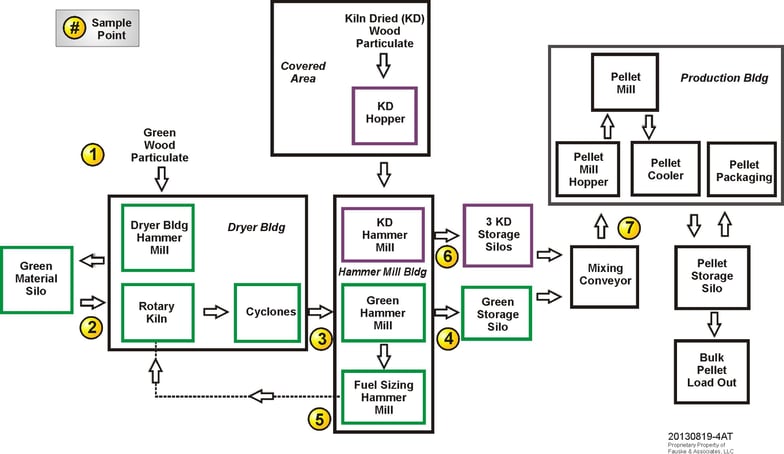
Figure 4. Process Flow Diagram
Table 1. Green Wood Particulate
|
Sample Identification |
Sample Point # |
Moisture content |
Mass Median Particle Size (µm) |
Particle Screening Result (µm) |
|
Storage Pile |
1 |
> 50% |
> 500 |
|
|
After 1st Size Reduction |
2 |
> 48% |
> 500 |
|
|
After Drying |
3 |
10.4% - 14% |
> 500 |
89% > 425 |
|
After 2nd Size Reduction |
4 |
9.4% - 13.4% |
> 500 |
77% > 425 |
|
After 3rd, Fuel Size Reduction |
5 |
1.3% - 3.1% |
> 500 |
70% > 425 |
Figure 5 provides the plant buildings layout. The Dryer Building is separate from the covered receiving area and the three other buildings that comprise the wood pellet processing facility. Green wood particulate is stored out in the open as shown in Figure 6. Different sources of green material are mixed under the covered area before being loaded onto feed conveyors going to the Dryer Building. A small front end loader takes KD wood particulate and feeds it onto a conveyor under the roof of the KD receiving area. Table 2 provides combustible dust test results for the green wood particulate after a third size reduction. This material is used as fuel for the rotary kiln.
 |
 |
|
Figure 5. Plant Buildings Layout |
Figure 6. Green Wood Storage |
Table 2. Combustible Dust Data for Fuel Wood Particulate
|
Sample Identification |
Mass Median Particle Size (µm) |
Pmax (bar) |
KSt |
Minimum Ignition Energy, MIE (mJ) |
Minimum Ignition Temperature, MIT (°C) |
|
After Fuel Size Reduction Sample point 5, As Received, 5kJ Igniter |
> 500 |
Did not Ignite |
Did not Ignite |
--- |
--- |
|
After Fuel Size Reduction Sample point 5, As Received, 10kJ Igniter |
> 500 |
6.6 ± 10%† |
31 ± 30%† |
> 1000* |
--- |
|
After Fuel Size Reduction Sample point 5, After ASTM E1226 Processing |
27 95% < 75 µm |
7.9 ± 10%† |
159 ± 12%† |
10 < MIE < 30 Es = 19 |
440 |
† Pmax and KSt determined with 10 kJ ignition energy. * 1000 mJ is the maximum energy the MIE test apparatus is capable of discharging.
The KD particulate is much smaller and drier than the green wood particulate and comes to the plant in closed trailers as shown in Figure 7. This KD particulate makes a single size reduction pass in the Hammer Mill building before storage for pellet making (see Figure 4). Table 3 presents moisture content, particulate size analysis, and combustible dust testing results for the KD wood particulate after size reduction (sample point 6 in Figure 4).

Figure 7. KD particulate in trailer for unloading
Table 3. KD Wood Particulate Sample Analysis
|
Sample Identification |
Moisture Content (wt.%) |
Mass Mean Particle Size (µm) |
Pmax (bar) |
KSt (bar-m/s) |
MIE (mJ) |
MIT (°C) |
|
Post KD Hammer Mill Sample point 6 |
2.6 |
27 95% < 75µm |
7.9 ± 10% |
152 ± 12% |
10 < MIE < 30 Es = 12 |
440 |
In the final phase of the process, green and KD particulates are mixed and fed into the pellet mills. Table 4 provides the combustible dust testing results for the mixed feed, after grinding to less than 75 microns per ASTM method E1226. The pellet fines collected by the Pellet Cooler Bag House did not require size reduction prior to analysis.
Table 4. Combustible Dust Data for Mixed Wood Particulate
|
Sample Identification |
Moisture Content (wt.%) |
Mass Median Particle Size (µm) |
Pmax (bar) |
KSt (bar-m/s) |
MIE (mJ) |
MIT (°C) |
|
Pellet Mill Feed† (Mixed KD and Green particulate, Sample point 7) |
2.6 |
24 97% < 75µm |
7.9 ± 10% |
174 ± 12% |
10 < MIE < 30 Es = 16 |
440 |
|
Pellet Fines |
2.5 |
26 97% < 75µm |
7.9 ± 10% |
182 ± 12% |
10 < MIE < 30 Es = 19 |
440 |
† Prepared before testing in accordance with ASTM E1226 (ground to < 75 micron)
Hazard Analysis
It should be noted that NFPA 664 defines “dry nondeflagrable wood dust” as wood particulate with a mass median particle size greater than 500 microns and having a moisture content of less than 25 percent (wet basis). While this definition is not supported by Fauske and Associates, LLC (FAI), as many test results have provided data contrary to this definition, it is in the standard and remains a factor for compliance analysis.
The green wood particulate does not provide a combustible dust deflagration hazard until it undergoes size reduction for the third time for use as rotary kiln fuel. Even then, the difficulty to ignite a cloud is apparent from the high Minimum Ignition Energy (MIE > 1000 mJ) and large mass median particulate size greater than 500 microns. Evan a 5 kJ igniter did not ignite the post fuel hammer mill sample. The low KSt, 31 ± 30% bar-meter/sec, produced when ignited by a fairly high energy source (10 kJ) is yet another indicator of the lower risk presented by the green wood particulate until it is mixed with KD particulate before pellet making. As noted above, this ignition data is contrary to the NFPA 664 definition of dry nondeflagrable wood dust as long it is not a result of overdriving the ignition in a 20 liter vessel.
The KD wood particulate, on the other hand, often arrives at the plant as a combustible dust and the design decision to process this material separately is prudent. KD wood particulate is easily lofted into the air and easily ignited, particularly by electrostatic discharge (see Table 3). An unprotected bag house serving the enclosed conveyor and the hopper in the KD wood particulate receiving area poses a higher risk of fire and deflagration as do the up-stream conveyors, Hammer Mill and silos. Employees unloading KD wood particulate were at an increased risk of exposure to deflagration from the receiving area equipment as well as to fire ignited by hot surfaces of powered industrials trucks used in KD wood particulate unloading.
An examination of vent calculations revealed that the existing vents were undersized based upon the new test results for KSt. The vent design relied on a KSt of 19 bar-meter/sec based on test data provided by OSHA’s Salt Lake Technical Center instead of 182 bar-meter/sec when determined by ASTM E1226 analysis.
Gap Analysis
The wood pellet corporation hired FAI to provide technical support in achieving NFPA compliance. First, FAI conducted an NFPA gap analysis of the facility, process, and programs. Gap analysis involves identifying and documenting the discrepancies between NFPA guidance or standards and existing implementation of equipment, practices and management systems.
The gap analysis identified several concerns that could be grouped into three broad categories:
- Protection for equipment handling combustible dust;
- Electrical area classification; and
- Safety management systems that are not current or do not exist.
Protection for Equipment Handling Combustible Dust
Some dust collectors at the facility did not have explosion protection installed. Where installed, the explosion protection vents were designed based on the OSHA KSt = 19 bar-meter/sec, instead of a value determined in accordance with NFPA 68 and ASTM Method E1226. This use of the grossly under-predicted value occurred despite a notation on the OSHA report not to use the reported KSt value for design calculations. (This KSt analysis was performed by OSHA during a previous enforcement action.) These vents also did not vent to a safe location. The vents pointed toward a wood particulate storage silo only 8 feet away. In addition, isolation was not present on most conveyors and air material separators.
In an effort to minimize fugitive dust, most conveyors were enclosed and under negative pressure provided by an air material separator. This allowed the conveyors to serve as air ducts allowing small particulate to be carried in the air stream while heavier particles rode the conveyor between pieces of equipment. This approach allowed the sufficiently small airborne particulate to by-pass the Hammer Mills, thus reducing mechanical and electrical loading of the mills. However, this design created long sections of unprotected or under-protected duct and equipment. To maintain this design feature, conveyors and some air material separators could not be protected by prescriptive means and required further analysis provided by the PHA.
The indoor bucket elevator, allowed by a permit variance to the building code by the local Authority Having Jurisdiction (AHJ) did not meet NFPA 654 requirements for pressure relief, ignition prevention, and preventing hazard propagation. This could have been corrected by installing deflagration vents, bearing monitors, and a self-adjusting belt alignment system, or by simply removing and replacing the indoor bucket elevator. FAI recommended and management accepted the latter option.
Another aspect of the plant design philosophy brought 100% of the equipment indoors, with the exception of conveyors between buildings. While preventing weather related impacts to the equipment, this brought equipment more typically located outdoors for safety purposes inside. This also raised concerns with the OSHA incident investigation team that suggested that the prescriptive approach at NFPA 664, Section 8.6.2.1 would require the rotary kiln to be relocated outside of the building.
8.6.2.1 Rotary dryers having a deflagration hazard shall be located in one of the following places:
(1) Outdoors
(2) In a separate detached building
(3) In a separate cutoff room with damage-limiting construction.
Other equipment issues were identified such as verifying that duct work and enclosed conveyors were properly sized, provided adequate air flow, and included tramp metal separation equipment.
Electrical Area Classification
The gap analysis included a review of the electrical area classification. The facility had electrical wiring, enclosures, conduits and outlets compliant with Class II Division 2 requirements. However, the facility did not have a documented electrical classification plan and did not use appropriately rated equipment such as powered industrial trucks in the Class II Division 2 space. Other spark producing equipment such as unrated portable vacuums should have also been prohibited.
Using NFPA 70, National Electric Code (NEC), Article 502 and NFPA 499, Recommended Practice for the Classification of Combustible Dusts and of Hazardous (Classified) Locations for Electrical Installations in Chemicals Process Areas, a point source method based on equipment location was used to create a classification plan for the facility. This plan identified a limited radius surrounding equipment as Class II Division 2 and provided housekeeping requirements and fugitive dust control measures to maintain this classification. Locations outside of the identified radius surrounding equipment were classified as general purpose. The plan also restricts non-rated equipment from being used in Class II rated areas. In some areas, this meant changes in equipment and procedures to comply with NEC rules, including obtaining a Class II Division 2 rated portable vacuum to be used for housekeeping.
Safety Management Systems
The gap analysis identified that written combustible dust management programs such as Management of Change (MOC), housekeeping, and preventive maintenance and inspections did not exist. Combustible dust training efforts were minimal and poorly documented.
FAI provided guidance for new policies, written programs, and training to be developed and implemented. It was verified that these new programs would meet recordkeeping and auditing requirements. With these policies and programs in place, a new comprehensive personal protective equipment evaluation was conducted. An important finding identified from this evaluation and later supported by the PHA, was providing fire resistant coveralls for employees unloading KD wood particulate.
Training sessions for plant management and supervisors were also conducted by FAI. Topics addressed included combustible dust awareness; inspections and maintenance requirements; combustible dust housekeeping with instruction addressing issues such as recommended cleaning techniques using natural bristle brooms, and prohibitions against creating dust clouds or using compressed air without all appropriate precautions taken first; timely fugitive dust control to stop leaks as soon as practical; and record keeping requirements for MOC, maintenance, and training. In turn, management repeated the training for production and maintenance employees.
This gap analysis identified many issues that could be corrected according to prescriptive requirements of NFPA 664. However, some issues were more complex, requiring further testing and evaluation to come up with a strategy to minimize the combustible dust hazard. FAI proposed a risk-based approach, mentioned in the NFPA standard as an acceptable alternative to the prescriptive actions mentioned, to identify and prioritize actions needed to reduce or mitigate risk. Below are some of the focus areas of the risk-based study:
- Sample and test wood particulate from critical plant areas;
- Provide training on combustible dust management and awareness;
- Perform a Process Hazard Analysis (PHA); and
- Implement PHA recommendations in a risk-ranked manner.
A risk-based approach using a PHA was used to address the issues as well as prioritize the items identified by the gap analysis.
Process Hazard Analysis (PHA)
Before performing the PHA, FAI spent time with the client to develop a Risk Management Matrix representative of their own risk tolerance. The risk matrix development addressed personnel and public safety, environmental protection, and business interruption or loss consequences from episodic events. This effort produced a detailed five-level-likelihood by seven-level-severity risk matrix. For each level of risk an urgency directive was established to identify the allowable time for follow up actions to be completed. Table 5 presents the Risk Description and Action Time Frame Matrix developed.
Table 5. Risk Description and Action Time Frame
|
Descriptor |
Action Priority |
Action to be Taken |
Recommended Time Frame |
|
Unacceptable Risk (Action required) |
A |
Risk reduction required; must take action to move the risk out of the A zone. |
Existing process: Target New or modified project: Resolve prior to startup. |
|
Marginally Acceptable Risk (Develop risk reduction plan) |
B |
Detailed analysis required; reduce scenario likelihood and/or severity by at least one order of magnitude or reduce/eliminate underlying hazard, unless demonstrated to be as low as reasonably practicable. |
As soon as practical
Target is 12-18 months to accomplish. |
|
Acceptable Risk (Given the circumstances) |
C |
Specify an appropriate action if a standard practice is violated or a readily implemented improvement (e.g. operating procedure) is identified; otherwise no action required. |
Standard practice and procedural changes. |
The PHA followed the HAZOP methodology to meet the hazard analysis requirement of NFPA 664. The scope included combustible dust hazard identification and consequence evaluation for the pellet manufacturing process from raw material receiving to packaging and bulk load out. The process was divided into 18 nodes according to process areas and control opportunities. For example, the kiln dried wood was divided into 4 nodes given as examples below. Green wood handling comprised 8 nodes, and mixed particulate and pellet forming through packaging/bulk load out consisted of 6 nodes (see Figure 4 for reference). For example, the KD nodes were as follows:
- Node 1, Receiving Kiln Dried (KD) Wood Particulate (WP),
- Node 2, Conveying KD WP from Hopper to Metering Bin,
- Node 3, KD Metering Bin to KD Hammer Mill, and
- Node 4, Filling Silos 1, 2, and 3.
FAI led the PHA team to identify hazards, consequences, and safeguards. Process parameters such as wood flow, air flow, equipment operation and signal flow were analyzed using both standard and process specific guide words. The team identified how deviations from the design intent could occur through unit malfunction or improper operation and the consequences that could occur for each scenario. Next the team assigned a risk ranking to those scenarios based upon estimates of severity and likelihood. Both the continuous operation of the process and the transient operations (start-up and shutdown) were included in the study.
One scenario identified a design control flaw where the green wood is metered into the rotary kiln during start-up operations. This scenario was later realized during start-up operations following maintenance shut down and resulted in a small fire before the recommended changes were implemented. In all, the PHA developed 54 recommendations in response to unacceptable and marginally acceptable risks identified (see Table 5).
Of note is that the PHA results did not agree that the rotary kiln presented a deflagration hazard based upon laboratory results on particle size, moisture content, personnel exposures, and the other combustible dust test results. Workers only entered the building briefly twice per shift to take equipment meter readings. Ultimately these meters were rewired and routed into the automatic data collection system and reported to the control center (remote location). The drying process in this building did present a fire hazard and the PHA recommended additional safeguards for fire mitigation. These safeguards were included in the corrective actions proposed to OSHA. Figure 8 provides a block flow sketch of the rotary dryer building.
OSHA requested that the facility hire an independent third party expert, from their proposed list of experts, to comment on the acceptability of the proposed corrective actions and their implementation as well as the PHA. The independent expert accepted the PHA’s conclusions and also satisfied OSHA’s concern regarding worker safety.

Figure 8. Rotary Dryer Building Block Flow Sketch
Conclusion
Using a well-defined testing strategy, gap analysis and PHA provided plant personnel an opportunity to understand hazards not previously realized and to determine the relative risk associated with those hazards. This approach engendered new ownership of the individual issues by the plant staff. By performing the gap analysis and PHA, a risk-based approach was applied to achieve and acceptable level of risk by implementing protective systems and safeguards. The PHA allowed the client to prioritize actions and assign responsible personnel to address recommendations and follow through on implementation. The client retained FAI to complete the same process at each of their other facilities.
We welcome questions and discussions. For more information, contact our team at dust@fauske.com.