
By Benjamin Doup, Ph.D., Senior Nuclear and Chemical Engineer, Fauske & Associates
 Flow regime characterization in emergency relief system (ERS) design is important because it can impact your required vent size and will impact the quantity and rate of liquid material that is vented.
The quantity and rate of liquid material that is vented will affect the design of downstream effluent handling equipment. The flow regime, in the context of emergency relief system design, refers to the interplay between vapor (and/or gas) and liquid phases in a vessel. The flow regime is a characteristic of the venting material during an emergency relief.
The Design Institute for Emergency Relief Systems (DIERS) program [1] contributed to the understanding of the behavior of the vapor liquid two-phase flow in vessels and supplied reasonably easy to use correlations that generally describe the two phase flow behavior. The resulting correlations are based upon a drift flux model [2-3] approach. The drift flux model treats the vapor and liquid phases as a single homogeneous mixture, but then describes the difference in velocity and the non uniform distribution of the two phases using constitutive correlations. The drift velocity, which models the velocity difference between the vapor and liquid, is defined as
(1)
where j = summation of the local vapor and liquid superficial velocities, m/s
ug = local vapor velocity, m/s
Vgj = vapor drive velocity, m/s
α = local vapor void fraction, -
⟨ ⟩ = indicates flow area leveraging, -
The distribution coefficient, which models the nonuniform distribution of the phases, is defined as
 (2)
(2)
where C0 = distribution coefficient, -
Two flow regimes were initially defined in the DIERS program [1] utilizing the drift flux model. These two flow regimes are bubbly and churn-turbulent flow regimes. Other flow regimes such as the wall boiling or foamy regimes exist, but these flow regimes are not discussed further in this article.
 The bubbly flow regime is characterized by smaller bubbles that are typically spherical or near spherical in shape with diameters generally less than 11 mm (for water). These bubbles have a large surface area to volume ratio and are fairly uniformly distributed in the flow field. Figure 1 shows an image of bubbly flow in a vertical air-water test section. Momentum is transferred between the vapor and liquid phases at the interface of the vapor bubbles. This indicates that an increase in the vapor bubble surface area results in tighter coupling between the vapor and liquid phases and the result is less disengagement between the vapor and liquid phases.
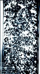
The churn-turbulent flow regime is characterized by larger bubbles that can be elongated and the flow structure is very turbulent partially due to bubble induced turbulence. These bubbles have a smaller surface area to volume ratio. Figure 2 shows an image of churn-turbulent flow in a vertical airwater test section. This image was obtained in a 2” diameter cylindrical test section, which is much smaller than most vessels and the wall can impact the flow structure. These wall effects are not as pronounced in  large scale vessels. The smaller surface area to volume ratio compared to the bubbly flow regime indicates that the vapor and liquid phases are not tightly coupled, resulting in more disengagement between the vapor and liquid phases for this flow regime. Figure 1 Image of Bubbly Flow in a Vertical Air-Water Test Section - Courtesy of Dr. B. Doup and Dr. X. Sun (The Ohio State University)
The form of the drift velocity used in the original DIERS program [1] is given by
 (3)
(3)
where m= 3 for the bubbly flow regime and approaches ∞ for the churn turbulent flow regime
n= 2 for the bubbly flow regime and 0 for the churn turbulent flow regime
u∞ = bubble rise velocity, m/s
Figure 2 Image of Churn-turbulent Flow in a Vertical Air-Water Test Section - Courtesy of Dr. B. Doup and Dr. X. Sun (The Ohio State University
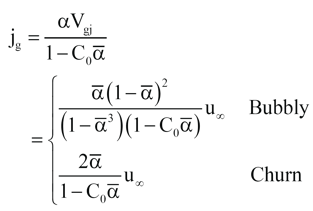
They related the vapor superficial velocity to the average void fraction by assuming the average vessel void fraction is equal to the local void fraction for bubbly flow and by averaging the void fraction in churn turbulent flow over the height of the two-phase mixture. Grolmes and Fisher [4] re-investigated these correlations and derived an alternative form of the bubbly correlation that was obtained without assuming the average vessel void fraction is equal to the local void fraction. The vapor superficial velocity relations from the original DIERS program [1] are given in Equation 4.
 (4)
(4)
where jg = vapor superficial velocity, m/s
α‾ = vessel average void fraction, -
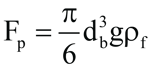
.jpg?width=162&name=Summer%202018%20PSN%20Final%20(2).jpg) The form of the bubble rise velocity is obtained by performing a force balance on a single bubble in an infinite medium (i.e., pressure force = body force + drag force). Figure 3 shows this force balance schematically.
The form of the bubble rise velocity is obtained by performing a force balance on a single bubble in an infinite medium (i.e., pressure force = body force + drag force). Figure 3 shows this force balance schematically.
The pressure force is defined in Equation 5
 (5)
(5)
where db = bubble diameter, m
Fp= pressure force, kg∙m/s2
g = acceleration due to gravity, m/s2
ρf = liquid density, kg/m3
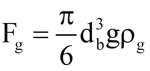
The body force is defined in Equation 6
 (6)
(6)
where Fg = body force, kg∙m/s2
ρg = vapor density, kg/m3
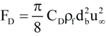
The drag force is defined in equation 7
 (7)
(7)
where CD = drag coefficient
FD = drag force, kg∙m/s2
The drag coefficient can be expressed as shown in Equation 8
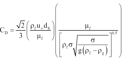 (8)
(8)
where μf = liquid dynamic viscosity, Pa∙s
σ = surface tension, N/m
The resulting bubble rise velocity is then
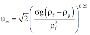 (9)
(9)
Researchers have replaced the √2 factor by experimentally determined coefficients. Peebles and Garber [5] (according to Wallis [3]) present the bubble rise velocity as
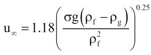 (10)
(10)
which was used in the DIERS program for the bubble rise velocity in the bubbly flow regime.
Harmathy [6] (according to Wallis [3]) presents the bubble rise velocity as
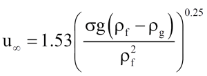 (11)
(11)
which was used in the DIERS program for the bubble rise velocity in the churn-turbulent flow regime.
The next logical question is how to determine flow regime for a new material or new mixture of materials? The only option at this point is to test your material under emergency relief conditions.
** See the fall 2018 Process Safety newsletter for a detailed flow regime testing approach and sample data.
References
- Fisher, H.G., Forrest, H.S., Grossel, S.S., Huff , J.E., Muller, A.R., Noronha, J.A., Shaw, D.A., and Tilley, B.J., Emergency Relief System Design Using DIERS Technology, The Design Institute for Emergency Relief Systems (DIERS ) – Project Manual, 1992.
- Zuber, N. and Findlay, J.A., “Average Volumetric Concentration in Two-phase Flow Systems,” Journal of Heat Transfer, November, 1965.
- Wallis, G.B., One-dimensional Two-phase Flow, 1969.
- Grolmes, M.A. and Fisher, H.G. “Vapor-liquid Onset/Disengagement Modeling for Emergency Relief Discharge Evaluation,” Prepared for Presentation at the AIChE 1994 Summer National Meeting , 1994.
- Peebles, F.N. and Garber, H.J. Chemical Engineering Progress, Vol. 49, pp . 88-97, 1953.
- Harmathy, T.Z. AIChE Journal, Vol. 6, pp . 281, 1960.
Dr. Benjamin Doup is a Senior Nuclear and Chemical Engineer in the Thermal Hazards department at Fauske & Associates. For more information or to discuss Emergency Relief System Design, DIERS, two-phase flow regimes, risk based inspection and other process safety concerns, please contact info@fauske.com or 630-323-8750.