Stainless Steel Piston Use
The Vent Sizing Package 2 (VSP2) and Advanced Reactive System Screening Tool (ARSST) are robust and versatile instruments that can be operated in a wide variety of ways to simulate numerous upset scenarios. A common upset scenario is a loss of cooling during an all-in addition of a reagent or catalyst. Oftentimes, these injections can be performed using standard laboratory syringes. There are instances, however, that this is not a safe or practical approach. If a reaction is expected to be instantaneous, or the test design requires an initial nitrogen overpressure, removing the requirement of the operator to dispense the material is crucial. Fauske & Associates utilizes various sizes of stainless steel pistons in these types of situations. Stainless steel pistons involve a tubular chamber as the syringe body and a piston and rod assembly to act as the plunger. These pistons can be loaded with the desired dosing material, and employs a nitrogen overpressure to dispense the material. These are very useful instruments to have, and this article walks through proper cleaning procedures, various modes of operations, and other tricks of the trade.
How to Determine Piston Hold-Up
When operating stainless steel pistons, it is inevitable that some of the material that is loaded into the piston will remain in the piston after the injection. The amount of material remaining in the piston is referred to as hold-up. The volume of hold-up remaining in the piston is dependent on the material and their properties (e.g. dynamic viscosity, vapor pressure, or potential interactions between the material and the piston o-rings), the pressure differential across the piston, and the dimensions of the piston being used.
The most accurate way to determine holdup is to test the exact setup that is planned (the quantity of material you want to dispense, the same pressure differential, same temperature, etc.). The difference between the piston after the injection and the dry piston weight is the mass of the hold-up. Adding the hold-up to the desired dosing mass will help to most accurately achieve the correct quantity.
Depending on the material, it is not always practical to do the approach above. If the chemistry is not very sensitive to small alterations of the recipe, assumptions on the holdup could be made. Alternatively, a suitable proxy material with similar material properties to that of the material of interest could be tested and could also yield accurate results. Regardless of the method used, be sure to clean the piston thoroughly so as not to contaminate the next sample being injected or alter the hold-up results.
What Kind of Backpressure to Use
The imposed backpressure used to depress the piston should be at least 100 psi greater than the pressure in the test cell to overcome friction. A backpressure of 200 psi greater than that of the test cell can be used to ensure a rapid injection of material. Note, the pistons do have a maximum pressure capacity of 1,000 psi, so the pressure imposed must remain less than this.
How to Clean a Piston
To ensure the integrity of the piston is not compromised and the next sample loaded is not contaminated, it is crucial to promptly clean the piston after use. The easiest and quickest way to clean a piston would be to thoroughly rinse it out shortly after using it with a suitable solvent by pulling the solvent into the piston and discharging it a few times until the fluid runs “clean”.
For example, if concentrated sodium hydroxide was injected with the piston, it should be rinsed with water until the water that comes out of the piston is a neutral pH. Following this step, the piston should be rinsed with acetone, or another suitable solvent to dry the piston, a few times. Finally, air should be pumped in and out of the piston to remove residual solvent. It is generally a good idea to leave the piston in a fume hood to ensure that all of the solvent evaporates before the next use.
If the dispensed material is particularly corrosive or toxic, a more thorough cleaning protocol is recommended. The best way to ensure the piston is completely clean is to take the piston apart and clean the interior parts and replace the seals.
 How to Disassemble a Piston
As stated above, it is important to thoroughly clean a piston if highly corrosive or toxic chemicals were used so the piston does not corrode and any health hazards are removed from the piston.
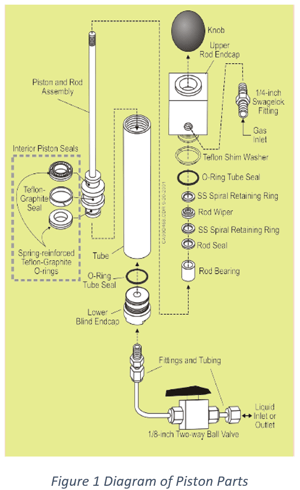
If a piston is leaking or needs to be thoroughly cleaned, it is simple to completely disassemble the pistons interior. A piston is composed of an interior piston and rod, an exterior tube, various seals, two endcaps, and fittings, as shown below.
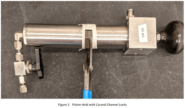
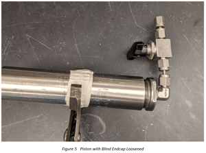
The first step is to remove the upper rod endcap. Hold the body of the piston with a pipe wrench or curved channel locks and use a wrench to loosen the rod endcap. Wrapping the piston with tape or a wipe can help protect the body from being scratched by the wrench used to hold it. Avoid clamping down on the body of a piston with a vice, as this could potentially compromise the maximum allowable working pressure of the piston.
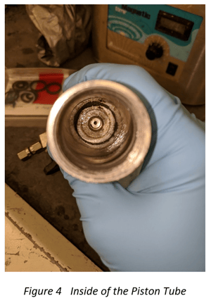
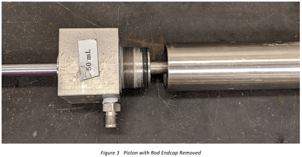 After the upper rod endcap is removed along with the piston and rod assembly, the interior of the tube can be cleaned.
The lower blind endcap does not necessarily need to be removed, but to remove it, gently place the piston in a pipe wrench and loosen the endcap with a wrench.
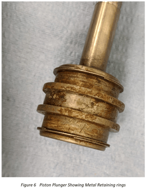
Make sure to carefully clean around all seals/o-rings/washers/retaining rings. Replace any pieces that appear damaged. The metal retainer rings can be easy to miss, especially when they are covered in grease. Make sure to replace these along with the seals.
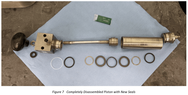
To completely rebuild the piston, it is helpful to match the shape of the seals removed to the new replacement seals. Pictured below is a disassembled piston with all the seals removed and the new replacement seals near where they should be placed. BEFORE placing the new seals, coat the grooves in vacuum grease to help ensure a good seal is made. If the piston is going to be used to inject corrosive materials, a chemically-resistant grease can be used instead, such as DuPont Krytox® grease, to help protect the piston and the integrity of the seals. The rebuild kits also come with a packet of green lubrication called Magnalube-G. FAI tends not to utilize this in favor of more chemically resistant lubrications, but the Magnalube is an acceptable lubrication for many applications. The technical data sheet can be found at magnalube.com.
On the upper rod endcap, there is a thin Teflon shim washer that goes above the threads and a black O-ring tube seal that goes in the groove beneath the threads. On the lower blind endcap, there is only a black O-ring tube seal that goes in the groove above the threads.
On the piston plunger, there are two spring-reinforced Teflon-graphite O-rings; make sure the springs face each other when installed and there is vacuum grease on the springs as well. These go on the ends on the piston. Between the spring-reinforced O-rings, there is a Teflon-graphite seal. The metal retaining rings go on the very ends of the piston plunger, and these helps keep the seals in place.
Once all the seals are in their proper place, the piston is ready to be reassembled. Rub vacuum grease into the threads on the tube and the endcaps before threading the endcaps back onto the tube. In the rebuild kit, there is a small sheet of red plastic shim paper. Lightly lubricate this and wrap it around the inner threads of the piston tube that the plunger will be pushed through. This is to protect the threads while the plunger is reinserted into the body. Remove and discard the shim paper once the plunger is past the threads.
Once the endcaps are threaded back on and tightened, it is a good idea to pressure check the piston to make sure the seals set properly. This can be done by depressing the plunger all the way, closing the valve on the blind endcap, and then imposing at least 200 psig through the rod endcap. If the plunger rises, that means there is a leak. Make sure everything is tightened and repeat; if it still rises, there is a leak in one of the seals and the piston needs to be opened up again.
It is possible that the plunger will not raise while the pressure is imposed on the piston, but it will raise when the pressure is vented. This is normal and NOT indicative of a leak.
How to Inject Samples at Elevated Temperatures
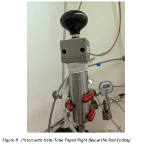
A common upset scenario involves heating a portion of the reaction mass to the processing temperature, and injecting a secondary component. When there is a temperature differential between the sample in the test cell and the component being injected, there is a sensible heat component to the overall measured heat, i.e. some of the exothermic heat from the reaction goes into heating up the colder injected component. To eliminate this, the injected sample can be preheated prior to injection. To warm the sample while it is loaded to the piston, the piston can be heat-traced. Note, the temperature limit of the piston’s seals is 400°F (204°C).
To heat the piston, FAI utilizes HTS/Amptek flexible electric heating tape. This is a heating element wrapped in a fiberglass overbraid. To power the heat-tape, FAI utilizes a VARIAC® variable transformer, which can control the voltage input into the heat-tape to control, which allows for a specific temperature to be targeted.
Start by wrapping the heat-tape/heating element around the top of the piston, right below the rod-endcap. Use heat-resistant Fiberglass electrical tape to keep the heat-tape in place.
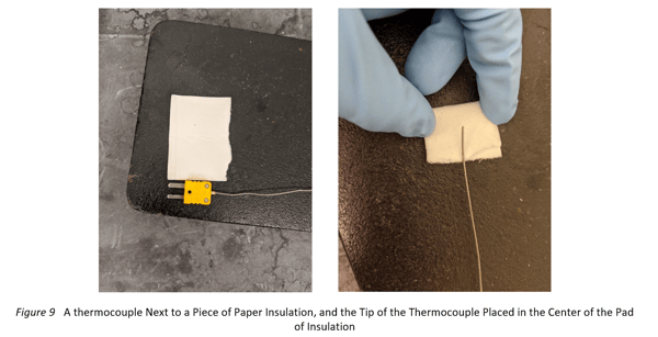
Once the heat-tape is secured to the piston, obtain a small piece of paper insulation and a thermocouple. Fold the paper insulation around the tip of the thermocouple, and tape it towards the bottom of the piston tube, with the thermocouple in direct contact with the piston. The insulation is so the thermocouple is measuring the temperature of the piston, rather than the heat-tape Add additional high-temperature tape to help secure the TC in place.
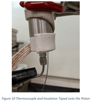 Now that the TC is taped into place, finish wrapping the heat-tape toward the bottom of the piston, and then tape it into place with more high-temperature tape. Be careful not to dislodge the TC from its position.
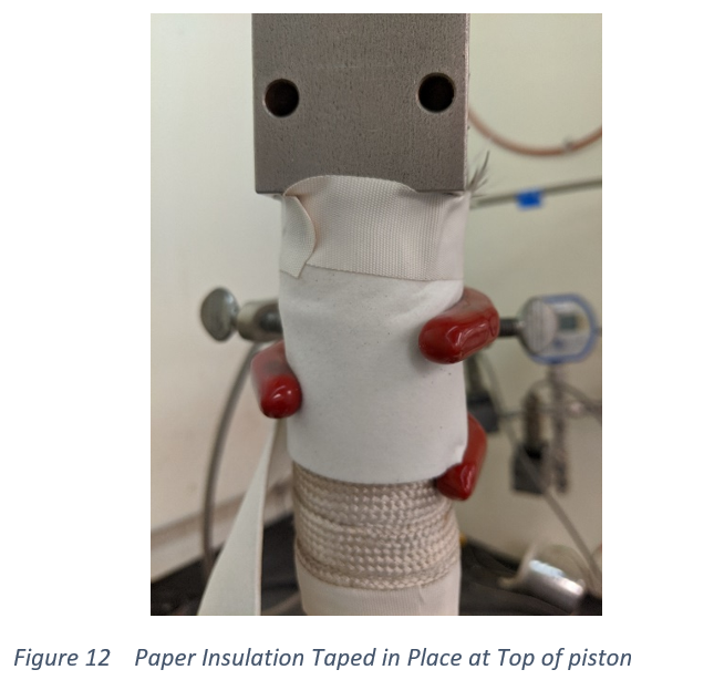
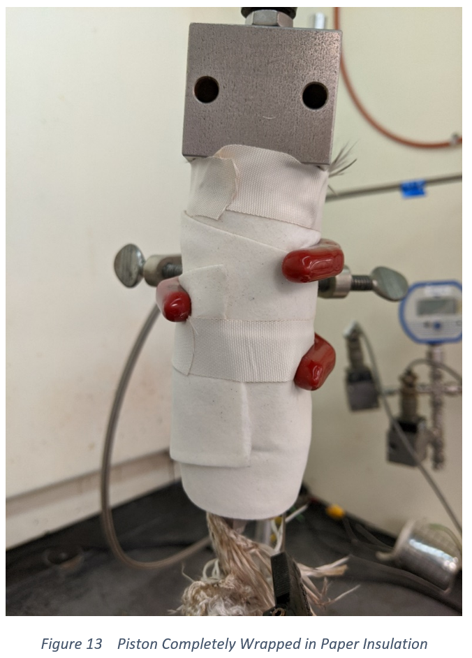
If the injection temperature is significantly higher than ambient temperature, insulate the piston to reduce heat-losses. To insulate the piston, wrap the strips of paper insulation used for wrapping the VSP2 test cell around the piston, making sure to compress the insulation to remove any air pockets, and tape them in place.
|
|
|
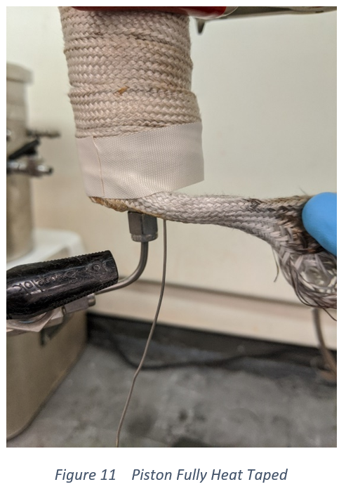
Any excess heat-tape can be wrapped around the fittings between the blind end cap and the injection port, and extra insulation can be used to insulate these parts of the piston as well. This can help reduce any heat losses from the material passing through the unheated fittings.
When the piston is heat traced and insulated, connect the heat-tape to a VARIAC® or other suitable power source. Once the thermocouple reads the desired temperature, it is a good idea to allow time for temperature equilibration to ensure the sample inside is also at that temperature. The length of time for equilibration varies on the material and target temperature.
How to Inject Samples at Sub-Ambient Temperatures
Sometimes the sample needs to be chilled, rather than heated, such as compressed gases that need to be injected as a liquid.
Preparing a cold sample takes less active time than wrapping a piston in heat-tape, but overall it takes more time as the entire piston needs to be chilled. However, this can be done before the sample is injected into the piston, such as the day before, or even first thing in the morning.
The piston should be flushed with nitrogen to remove moisture present in the air, and then the inlet should be capped. Once that is done, simply put the piston in a bag and place it in a freezer. The bag is to help protect any fumes from coming into contact with the piston and to minimize frost forming on the piston, as well as containing and fumes that might escape the piston once the sample is loaded into the piston.
Once the piston is sufficiently chilled, it can be removed from the freezer and the sample can be loaded. Make sure to wipe off any frost on the outside of the piston so the measured masses are accurate. Once the sample is loaded, put it back in the freezer until you are ready to inject the sample. Keep in mind that cold metals pose their own hazards, and proper precautions should be taken to protect oneself.
General Tips for Piston Use
- When opening the valve after injecting chemicals, make sure the opening is pointed toward the back of a fume hood or into a waste container, as their still might be pressurized liquid in the piston that will expel forcefully
- When loaded compressed gases, the sample cylinder may get cold. Wear proper PPE to protect against the cold metals of the sample cylinder and chilled piston
- Be cautious of potential interactions between the sample injected and the solvents used to clean/rinse the piston. Pressure may build in the piston as a result of these interactions
- Pressure check the piston before each use. It is important to make sure the chemicals stay contained in the piston
- Even if there are no leaks and the chemical is contained in the piston, proper PPE should be worn when handling the piston as if you were handling the chemical. Mistakes can happen and it is best to be prepared for them
- If a more controlled injection of the sample is desired, a needle valve can be used instead of a ball valve to reduce the flow orifice
- Make sure the valve on the fill line and the valve on the piston do not interfere with each other when opening the valve. If they do, simply rotate the valve on the piston so the handle is not in-line with the handle of the other valve.
To get any questions answered, please reach out to contact the Fauske Team below!