
Abstract
The sudden opening of a relief device during an overpressure event will cause the relief piping to experience dynamic loads. A pressure wave may be generated that travels at the speed of sound through the fluid. This has led to force imbalances, particularly on long pipe segments, that can potentially damage the relief system or prevent the relief system from operating properly. In order to design and properly protect the relief piping with the necessary supports, it is critical that a detailed analysis of the dynamic loads (e.g. thrust, momentum, and wave) following the opening of a pressure relief device is performed. In many cases, simple analytical techniques may not be appropriate and a time history analysis of the loads acting on the relief system may be required. To address this phenomenon, an evaluation of the dynamic loads using RELAP5 (Reactor Excursion and Leak Analysis Program) software will be discussed. The RELAP5 software can be used to analyze fluid transients and compute resulting loads. It is possible to evaluate systems undergoing single phase or two phase relief using water as the fluid.
1. Introduction
This paper summarizes a methodology that can be used to size and verify the design of emergency relief systems for chemical reactors, with a focus on reaction force calculations. The methodology consists of multiple steps that include calorimetric trials, fluid dynamics, and structural calculations. The example plant is a three reactor site that produces phenolic resins. During a hypothetical process hazard analysis (PHA), it was determined that a loss of cooling prior to the catalyst addition could lead to overpressurization of the vessels. In response, calorimetric trials were performed and the data obtained were used to evaluate the required size of the relief device.
The characterization of the runaway reaction was then used in a fluid dynamic assessment which provided the reaction forces. The reaction forces were used as input to the structural analysis. The fluid forces were computed with the RELAP5 software and the structural assessment was performed in PIPESTRESS. The adequacy of the structural design was finally evaluated in accordance with the rules of an appropriate piping code.
2. Testing
The data to be used for relief sizing was collected using the Vent Sizing Package 2TM (VSP2) which is designed to acquire thermal and vent sizing data [2,3,4,5]. The VSP2 utilizes a low phi-factor test cell, thus providing near adiabatic runaway conditions. As a result, the temperature and pressure data measured in the VSP2 are directly scalable to any process vessel.
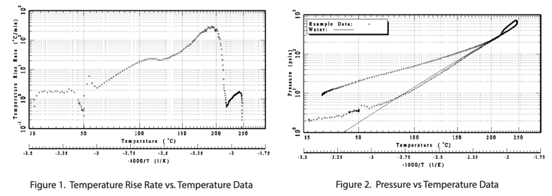
The system that was evaluated in this example is a base-catalyzed phenol-formaldehyde reaction. The recipe uses a 2.2:1 molar ratio of formaldehyde to phenol. The upset scenario that was tested was a loss of cooling prior to the addition of the catalyst (50% caustic). The phenol and 34% formaldehyde solution were added to the test cell. The contents were then heated to the process temperature of 50°C. The catalyst was injected into the test cell and the sample was kept adiabatic. The temperature rise rate data are shown in Figure 1. The initial exotherm was caused by the heat of mixing of the catalyst itself, followed by the runaway cross-linking polymerization reaction which produces the phenol-formaldehyde resin. The pressure vs. temperature data are compared with vapor pressure data for water, taken from DIPPR® [1], and shown in Figure 2. The pressure profile indicates that the system very closely follows the vapor pressure of water as the temperature rises. The test data indicate that a possible overpressure hazard exists for the process vessel. Consequently, the process vessel should be evaluated for proper overpressure protection provided by the pressure relief system.
3. Relief Size Evaluation
The required relief size was evaluated for vessel R-3 which is used for the production of phenolic resin. The vessel has a volume of 5 m3 and contains 4 m3 of reactant. The vessel maximum allowable working pressure (MAWP) is 30 psig and the rupture disk set pressure is 10 psig. The relief system consists of a rupture disk located just downstream of the reactor nozzle, which leads to a common header and then to a catch tank. The relief system is assumed to have an equivalent length of 300 feet. Based on the upset scenario tested, a vent sizing calculation was conducted using Leung’s ω-method (available in our FERST software) assuming homogeneous vessel venting [6]. The data indicate that the system behaves as a vapor system in the venting region of interest. The analysis confirms that the 16 inch diameter rupture disk and pipe would be adequate to prevent overpressurization of the vessel. After the size of the relief system pipe has been determined, the evaluation can proceed to the mechanical analysis, which begins with calculation of the fluid forces.
4. Evaluation of Fluid Forces
Once the upset scenario has been quantified, a fluid model is used to evaluate the loads resulting from the postulated rupture disk bursting. The fluid forces are calculated using the RELAP5 computer code. RELAP (Reactor Excursion and Leakage Analysis Program) is a light water reactor transient analysis code developed for the United States Nuclear Regulatory Commission (US NRC) for simulation of a wide variety of hydraulic and thermal transients in both nuclear and nonnuclear systems involving mixtures of steam, water, non-condensable gases and solutes under single phase and two phase conditions. For this example, it was found that it is reasonable to assume steam/ water properties due to the absence of specific knowledge of the fluid properties during the transient. The chemical reaction in the vessel may cause the effluent properties to rapidly change during the transient. The accuracy of the reaction force prediction depends on the density and sonic velocity (in the liquid and gas phase) of the fluid. Therefore, the use of steam/water properties can provide a best estimate solution for the reaction forces.
The capability of RELAP5 has been validated for the analysis of hydrodynamic loads in steam/water induced by large and rapid pressure waves propagating with the speed of sound along piping systems [7]. The code was also validated by the US NRC for use in analyzing the propagation of pressure waves in piping systems [9]. Comparison of the results demonstrated suitability of RELAP5 to be used for computational problems involving propagation of pressure waves in piping systems such as reactor relief system design.
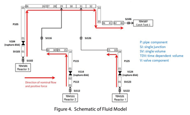
At the example plant, the emergency relief lines from each reactor are tied into a header pipe that feeds the catch tank. The catch tank is vented to the atmosphere. The pipe diameters are 8 inches for reactor 1, 12 inches for reactor 2, and 16 inches for reactor 3 and the header pipe. Figure 3 provides a schematic of the plant layout.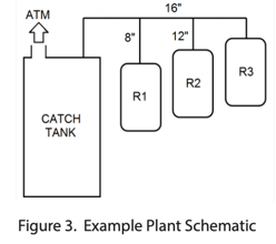
The burst disks are located at the reactor’s extraction nozzles. A numerical model is then built that presents the outlined relief system. It is important to note that the calculation time step and node size must be properly selected. Therefore, the model was finely nodalized to allow the detailed computation of hydrodynamic loads on pipe segments throughout the system. For example, the length-to-diameter ratios (L/D) were set close to unity for each node. A maximum time step was selected that is below the acoustic courant limit to ensure the fidelity of the transient hydrodynamic loads simulation. The maximum time step must be less than the time for the acoustic wave to travel with the speed of sound through a nodal volume.
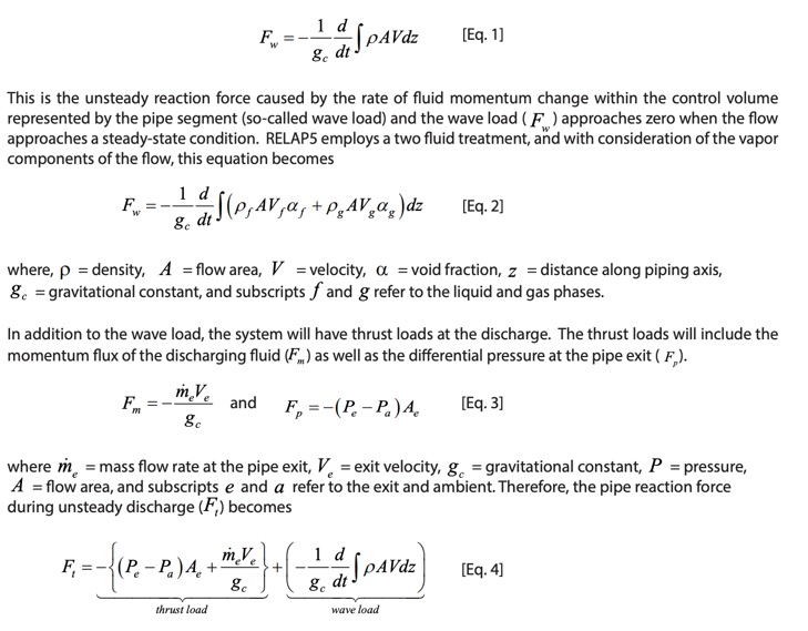
The runaway reaction is assumed to occur in a single reactor. However, simulation of global venting scenarios is possible. The reactor was initialized with a two phase mixture. The piping and catch tank downstream of the rupture disk were assumed to contain air at ambient conditions. Before the transient calculation begins, a steady state calculation with no flow is performed so that the model can initialize. The rupture disk burst is postulated by opening an arbitrarily modeled valve. Thereby, it is possible to change the rupture disk opening time. In this case, it was assumed that the rupture disk fully opens within 10 ms. Given the short duration of the depressurization transient, no heat transfer was assumed across the piping wall. However, heat transfer can be considered, if needed. The resulting fluid densities, void fractions, velocities, and pressure time histories are used to compute the reaction forces. A schematic of the fluid model is shown in Figure 4.
The development of the transient force-time history information for application to structural analysis models is based on the general force equations for a container [10]. The generalized force equation in one-dimensional form can be resolved by a pipe segment bounded by two elbows as
This is the unsteady reaction force caused by the rate of fluid momentum change within the control volume represented by the pipe segment (so-called wave load) and the wave load ( ) approaches zero when the flow approaches a steady-state condition. RELAP5 employs a two fluid treatment, and with consideration of the vapor components of the flow, this equation becomes
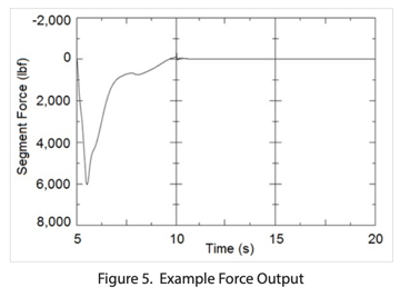
The generated time history data is now used to compute the force time histories on each pipe segment bound by elbows. Figure 5 shows example force output for the vent pipe at the burst disk at reactor 3. All force time histories are then applied in the PIPESTRESS model as force vectors for final design verification.
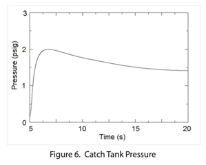
The catch tank pressure (Figure 6) is also monitored to verify that the MAWP is not exceeded. The backpressure can be monitored in any location of the relief system including attached vessels.
5. Pipe Stress Analysis
A structural computer model of the example plant is generated in the PIPESTRESS software. All information required for the model can typically be found on pipe isometric drawings. PIPESTRESS is an analysis program for nuclear and industrial piping. It can be used to evaluate the load cases that are needed to meet compliance with piping codes such as ASME B31.3. In addition to the pipe sizes and pipe segment lengths (from the previous step) one must now specify the pipe support systems as well as material properties. The example plant has one sliding support (one degree of freedom restricted) at the high point near reactor 1 and one sliding support above the catch tank. In addition, bellows are used at the reactor exit nozzles and the catch tank entrance nozzle. The bellows help to compensate displacements caused by the depressurization transient. The pipe supports are modeled as springs with constant stiffness. In that case, mounting hardware, such as anchor bolts, should also be evaluated. Force, pressure, and temperature time histories are imported from the previous analysis step. The example plant is then verified for thermal expansion, dead weight, and the hydrodynamic depressurization loads resulting from the rupture disk bursting. The resultant stresses from the different load cases are divided by the allowable stress for the material to obtain the usage factors for the pipe segments and pipe supports. The highest allowable value for a usage factor is 1. Figure 7 shows the final result of the structural analysis.
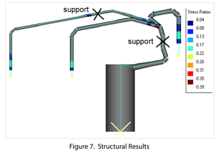
One can see that the maximum usage factor (stress ratios) is below 1, which indicates that the relief system design is adequate. The highest stress ratio (0.39) occurs at the tee connections, which is due to bending stresses and stress concentrations.
6. Conclusion
A solution for relief system design verification was presented, with a focus on demonstrating that RELAP5 can be used to model and quantify the reaction forces on the relief system during depressurization. The methodology utilizes a combination of laboratory testing, fluid dynamics and structural mechanics analyses. The engineering portion of this methodology uses established industry tools that have been extensively validated for these applications. Hence, application of this methodology provides confidence in the relief system design.
