
By: Jaehyok Lim, Ph. D., Nuclear Engineer, Basar Ozar, Ph. D., Nuclear Engineer and Sung Jin Lee, Ph.D.
Senior Consulting Engineer, Fauske & Associates
Current CRD Housing Model in MAAP
Modular Accident Analysis Program (MAAP) is an Electric Power Research Institute (EPRI) owned and licensed computer program that simulates the response of light water and heavy water moderated nuclear power plants for both current and Advanced Light Water Reactor (ALWR) designs during a severe accident. MAAP represents the integral behaviors of severe accident conditions that include overheating of core material, oxidation of the high temperature core materials in a steam environment, relocation of molten materials from the core region into the lower plenum, the subsequent failure of the Reactor Pressure Vessel (RPV) and accumulation of the core material in the containment, along with the molten core concrete interactions that would accompany this latter relocation.
Currently, the Boiling Water Reactor (BWR) version of MAAP code considers the response of Control Rod Drive (CRD) tubes inside the reactor vessel but does not explicitly model the section of CRD tubes beneath the reactor vessel. Instead, the code calculates and imposes the effective heat transfer coefficient as the boundary condition on the outer surface of the reactor vessel lower head. The effective heat transfer coefficient represents the thermal radiation and leakage in the lower head reflective insulation.
Normally, the heat loss through the lower head is small and accounts for only about 10% of the total heat generated in the reactor vessel. However, after a significant fraction of core has relocated to the lower plenum during a severe accident, a more accurate heat transfer calculation in the lower head is needed. Explicitly modeling the CRD housing beneath the reactor vessel can address this need. Also, it is possible for melt in the debris bed in lower plenum to overflow into failed CRD housings. The melt will travel some distance beneath the reactor vessel before it freezes, plugging the annular gap in the tube. The decay heat in the corium plug has to be dissipated through the tube wall. If the tube wall becomes sufficiently hot, it can fail by creep rupture, leading to vessel failure.
Evaluating this phenomenon requires modeling the heat transfer between the lower head, CRD tubes, pedestal gas and the pedestal wall, including the corium penetration distance and decay heat in the corium plug.
Another motivation for explicitly modeling the CRD tubes below the reactor vessel is to determine the mass of CRD tubes melted due to corium jet after vessel failure. The amount of melted CRD tube affects the mass and composition of the debris bed in the containment floor after vessel failure.
New CRD Housing Model in MAAP
Currently, the CRD tubes in the lower plenum are nodalized in up to 100 radial channels, consistent with the core radial nodalizaiton, and 100 axial nodes, consistent with the lower head axial nodalization. Typically six radial channels and twenty-five axial nodes are used to model the CRD tubes. In the new CRD tube model, the axial nodalization is extended below the reactor vessel to the CRD support bar level. Up to twenty axial nodes are allowed to model the extension between the support bar and the vessel inside bottom. Typically ten axial nodes are used.
Conduction and thermal radiation heat transfer from the lower head to the CRD tubes are considered. The heat capacity of the inner cylinder in the CRD tube is not considered, a conservative assumption. Conduction heat transfer along the CRD tube wall is considered. Convection heat transfer between the CRD tubes and pedestal gas is considered. Thermal radiation between adjacent CRD tubes and with the pedestal wall is considered.
The heat transfer area of the lower head facing the pedestal gas is reduced by the area occupied by the CRD tubes. The effective thermal coefficient on the lower head is kept the same.
After the CRD tubes inside the reactor vessel collapse, the thermal radiation from the corium crust to the inner surface of the CRD tube below the reactor vessel is considered. When the debris in lower plenum re-melts, the melt overflows into the annular gap of CRD tubes. The penetration distance for refreezing of molten debris within the tube wall is determined. The decay heat in the plugged CRD tube is added to the tube wall. The creep damage fraction of individual CRD tube wall is tracked. The detailed heat transfer calculation in the CRD tubes below the reactor vessel is performed until vessel failure.
After vessel failure, the CRD tube melting due to the exiting corium jet below the reactor vessel is considered. MAAP considers several failure mechanisms including failure of the In-Core Instrumentation (ICI) tubes or Traversing In-core Probes (TIPs), creep failure of the closure welds for the ICI penetrations or CRD tubes, and creep rupture of the reactor vessel lower head. Each of these failure conditions has initial failure location and size. Following the initial failure, the flow of molten corium through the failure opening would cause substantial ablation of the opening. According to the MAAP results, the radius of the failure quickly grows to 10 to 30 cm.
The molten corium discharged through the failure opening would attain sufficient velocities and have enough superheat to melt CRD tubes and support structure below the vessel that are in the path of the corium flow [Epstein et al. (1976), and Pilch and Tarbell (1985)]. The analysis of Chu et al. (1992) also shows that the surfaces that are affected by the molten corium jet heat up to the melting temperature within 15-30 seconds of initial contact and start melting. Therefore, the ex-vessel CRD tube melting model assumes complete melting of CRD tubes in the direct path of the molten corium jet.
The portion of the CRD tubes that is affected by the molten corium jet can be estimated using a geometric relationship. The molten corium jet initiated by the failure of an instrument tube is assumed to be located in between CRD tubes as shown in Figure 1. The molten corium jet grows until it reaches the outer surface of the CRD tubes and continues to grow, potentially covering four CRD tubes. The total melted mass is related to the ablated area assuming a homogenous mass composition of the CRD tube.
The result is shown in Figure 2 for a molten corium jet with different radii when the distance between the CRD tubes is 0.305 m and the outer diameter of the CRD tubes is 0.152 m. There is no overlap between the molten corium jet and the CRD tubes until the molten corium jet radius grows to 0.14 m. Then, the overlapping area grows until the four CRD tubes are ablated when the molten corium jet radius reaches 0.292 m.
In the second scenario, the molten corium jet is initiated by the failure of CRD tube closure weld as shown in Figure 3. The overlap area between the molten corium jet and the adjacent CRD tubes is shown in Figure 4. There is no overlap between the molten corium jet and the CRD tubes until the molten corium jet radius grows to 0.23 m. Then, the overlapping area grows until eight adjacent CRD tubes are ablated.
Results – Ex-Vessel CRD Tube Heat Transfer
The BWR-MARK I simulation results with and without the ex-vessel CRD tube heat transfer model are examined to evaluate the impact of the model. As shown in Table 1, the ex-vessel CRD tube heat transfer model is invoked when the control flag IEQ1HT is set to one or two. The decay heat of the corium plug in CRD tubes is considered when IEQ1HT is set to two.
Table 1 Control Flag to Invoke Ex-Vessel CRD Tube Heat Transfer and Melting Models
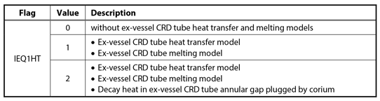
When IEQ1HT = 0, convection heat transfer between the ex-vessel CRD tubes and the pedestal gas is considered. Axial conduction along a CRD tube is suppressed after the CRD tube collapses inside the vessel.
In general, the ex-vessel CRD tube heat transfer model has little impact on the time of CRD tube collapse and vessel failure. After the isolation condenser (IC) stopped working, the core became uncovered at around 10,500 seconds. The CRD tubes inside the vessel collapsed at around 38,000 seconds and the vessel failed at around 47,600 seconds. Note that corium melt overflow into CRD tubes prior to vessel failure did not occur in this simulation.
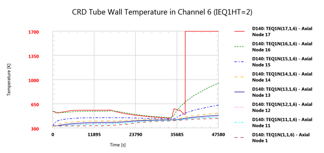
Figure 5 through Figure 7 show the CRD tube wall temperatures in channel 6 (outermost channel). Note that axial node 16 is in contact with the lower head (green curve). Therefore, axial node 17 is the lowest CRD axial node inside the vessel (red curve). Its temperature is set to the steel melting point, 1,700 K, when the CRD tubes inside the vessel collapsed. Note that only a couple of nodes below the vessel, nodes 16 and 15, were affected by the lower head temperature; nodes 14 and below followed the pedestal gas temperature. The results for IEQ1HT = 1 (Figure 6) and IEQ1HT = 2 (Figure 7) are identical because corium ingress into the CRD annular gap did not occur in this simulation.
Table 2 shows the heat balance in the debris bed in lower plenum at the time of vessel failure. When the vessel failed at around 47,600 seconds, the heat transfer rates in the debris bed in the lower plenum were 3,935 kW to RPV internals by thermal radiation, 73 kW to the pedestal gas through the lower head insulation, 38 kW through CRD tubes to the pedestal gas and 161 kW through CRD tubes to the pedestal wall. Without the ex-vessel CRD tube model (IEQ1HT = 0), the heat transfer rates in the debris bed were 3,961 kW to RPV internals by thermal radiation and 78 kW to the pedestal gas through the lower head insulation. Hence, although explicitly modeling the ex-vessel CRD tubes increased the downward heat transfer rate significantly, most of the heat generated in the debris bed was radiated upward to RPV internals and the additional downward heat transfer rate through the CRD tubes did not affect vessel failure. Moreover, the debris in the lower plenum was still heating up when the vessel failed as shown by the large difference between the decay heat and the total heat transfer rate in the debris bed (5,857 kW versus 4,207 kW). Therefore, the heat capacity of the debris bed and the amount of water in the lower plenum are more important in determining vessel failure than the downward heat transfer rate through the lower head and CRD tubes.
A sensitivity run was performed to delay vessel failure so that corium melt overflow into CRD tubes can be observed. When the local corium became molten at around 56,000 seconds, about 335 kg of corium flowed into the channel 6 CRD tubes. The molten corium penetrated the CRD tube about 0.4 m before it froze, plugging the CRD. The decay heat of the plugged corium was added to the CRD tube wall. The decay heat of the corium in the lower plenum was reduced by the same amount. Vessel failure due to the ex-vessel corium plug in CRD tubes was not predicted. Thermal radiation to adjacent CRD tubes and to the pedestal wall, and axial conduction in the tube wall were sufficient to remove the decay heat.
Results – Ex-Vessel CRD Tube Melting
A sensitivity run was performed to delay vessel failure so that melting of ex-vessel CRD tubes due to the corium jet after vessel failure can be observed.
The vessel failed at around 57,000 seconds due to the instrument tube penetration failure at the lower head axial node 7, which is in contact with the CRD tube radial channel 6, axial node 17. The failure opening radius grew quickly to 0.294 m due to ablation. At around 60,000 seconds, 695 kg of ex-vessel CRD tubes has melted, consisted of 125 kg chromium, 514 kg iron and 56 kg nickel. The total masses of metal in the debris on the pedestal floor were 153 kg chromium, 4,850 kg iron and 74 kg nickel.
Conclusion
The CRD tubes below the reactor vessel were explicitly modeled in MAAP in order to improve prediction of vessel failure and debris composition on the containment floor. The BWR-MARK I simulation results show that explicitly modeling the ex-vessel CRD tubes had minor impact on the vessel failure time. A penetration distance of 0.4 m was predicted when the corium melt overflowed into the collapsed CRD tubes. Nevertheless, the corium plug did not cause creep rupture of the CRD tube wall, which could lead to vessel failure. Upon vessel failure less than 1,000 kg of CRD has melted due to the corium jet, contributing to about 14% of the steel mass in the debris bed on the containment floor.
Table 2 - Temperature and Heat Balance of Debris Bed in Lower Plenum at Time of Vessel Failure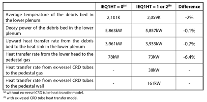
References
Chu, C. C., Sienicki, J. J., and Spencer, B. W., 1992. The Effects of Below-Vessel Structure and Water on Ex-Vessel
Melt Arrival Conditions in a Mark I Containment. Proceedings of NURETH5, Salt Lake City.
Electric Power Research Institute (EPRI), 2016a. Modular Accident Analysis Program (MAAP5) Boling Water Reactor
(BWR) and Pressurized Water Reactor (PWR) Lower Plenum Model Improvements: Japanese Fiscal
Year (JFY) 2015 Project. Product ID 3002007466.
Electric Power Research Institute (EPRI), 2016b. Modular Accident Analysis Program (MAAP5) Containment Model
Improvements: Japanese Fiscal Year (JFY) 2015 Project. Product ID 3002007467.
Epstein, M., Grolmes, M. A., Henry, and R. E., Fauske, H. K., 1976. Transient Freezing of a Flowing Ceramic Fuel in a
Steel Channel. Nuclear Science and Engineering 61, 310-323.
Pilch, M., Tarbell, W. M., 1985. High Pressure Ejection of Melt from a Reactor Pressure Vessel, The Discharge Phase,
Revision 7. NUREG/CR-4383-REV.7 (SAND-85-0012-REV.7).
Figure 1 - Interaction of Molten Corium Jet and Ex-Vessel CRD Tubes due to Vessel Failure between CRD Tubes
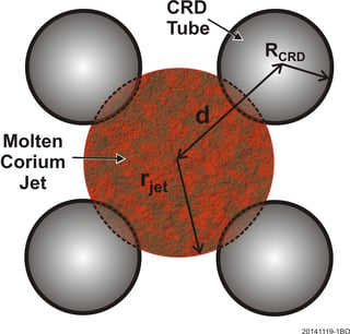
Figure 2 - Ex-Vessel CRD Tube Ablated Area and the Molten Corium Jet Area
Initiated by Instrument Tube Failure due to the Molten Corium Jet
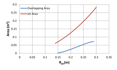 Figure 3 - Interaction of Molten Corium Jet and Ex-Vessel CRD Tubes due to Vessel Failure at the Location of a CRD Tube
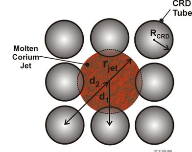
Figure 4 - Ex-Vessel CRD Tube Ablated Area and the Molten Corium Jet Area Initiated by
CRD Tube Closure Weld Failure due to the Molten Corium Jet
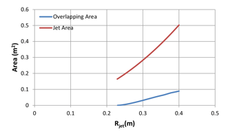
Figure 5 - CRD Tube Wall Temperature without Ex-Vessel CRD Tube Heat Transfer Model
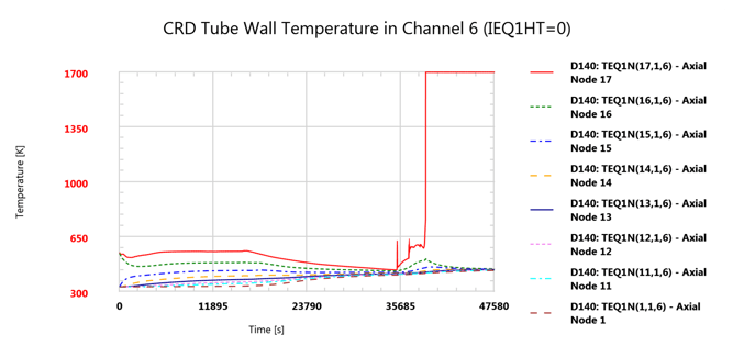
Figure 6 - Interaction of CRD Tube Wall Temperature with Ex-Vessel CRD Tube Heat Transfer Model
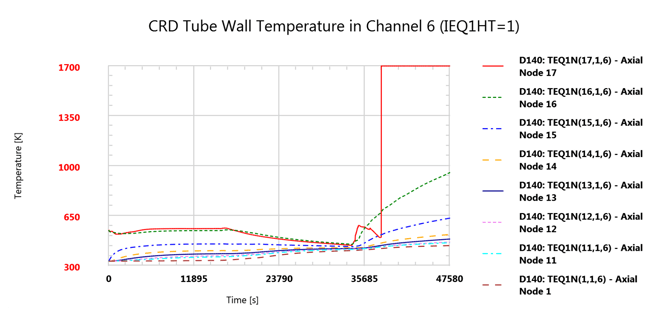
Figure 7 - CRD Tube Wall Temperature with Ex-Vessel CRD Tube Heat Transfer Model Considering Decay Heat of Corium Plug
For more information, contact: Sung Jin Lee, Senior Consulting Engineer, (630) 887-5205, lee@fauske.com


