By Jim Burelbach, PhD, Chief Commercial Officer, Fauske & Associatesand Marty Plys, DSc, Chief Technology Officer, Fauske & Associates |
|
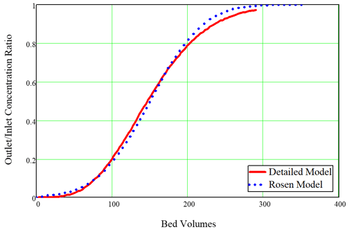
Fauske & Associates, (FAI) developed a computational fluid dynamics (CFD) model for performance of ion exchangers (IX) as part of our support for recovery from the March 11, 2011 tsunami and reactor melt-down accidents at the Fukushima Diaichi plants in Japan. In the immediate aftermath of the accidents, after water supply to the damaged reactors had been restored, contaminated water began to accumulate in the lower elevations of the reactor building structures. Tokyo Electric Power Company (TEPCO) recognized that the accumulated water would soon need to be decontaminated, and Toshiba Corp. was hired by TEPCO to solve this problem. FAI participated in the Toshiba “War Room” effort and was assigned to provide the technical basis for design of the water cleanup system, which was eventually named the SARRY system. The FAI IX model was developed and created under our NQA-1 compliant Quality Assurance procedures during our War Room service. The key output of our model was the estimate of the changeout frequency of the ion exchange modules (IXMs) and thus the cost estimate for the number of IXMs required for a campaign to remove accumulated water. These estimates were provided to TEPCO as part of the cost proposal for the SARRY system, which has been successfully implemented and operated since the summer of 2011. The FAI IX model has evolved since our 2011 experience, and we are in the process of upgrading the model to extend its capabilities for more general severe accident applications and for commercial non-nuclear applications. The present article describes the kinds of problems the model can solve now and provides some particular examples. The SARRY version of the FAI IX model considered only one ion type and one adsorber particle type. The extended model will consider multiple ions and multiple particles, which includes consideration of the particle size distribution of adsorber particles. Here we will show examples of the kinds of results that can be obtained for a single ion and adsorber. The key ions of interest for removal for SARRY were cesium and strontium. It is difficult to remove these ions from solution when there are competing ions from the same columns of the periodic table, namely, Na and K in the case of Cs, and Ca in the case of Sr. Furthermore, pH itself can have an influence on the performance of an ion exchange medium. The ability to remove an ion is quantified by a parameter known as the distribution coefficient, given the symbol Kd. This is the ratio of the equilibrium solid concentration and the equilibrium liquid concentration. Since it is traditional to express the solid concentration as moles/kg and to express the liquid concentration as moles/L, the units of Kd are usually quoted as L/kg. The typical ion exchange media for removal of alkali metal ions are naturally found inorganic zeolites such as clinoptilolite and chabazite. During the 1990s the US DOE successfully developed a highly effective synthetic zeolite material called crystalline silico-titanate (CST), which proved to be highly selective for removal of Cs and Sr even in the presence of very high concentrations of Na and K. This research was motivated by desire to remove contamination from waste at Hanford and Savannah River DOE sites. The key issue for cleanup of Fukushima contamination removal was that seawater had been used temporarily for cooling water injection, and therefore the accumulated contaminated water had high concentrations of Na, K, and Ca. Thus, the CST product developed by DOE was ideal for the SARRY system. The Quality Assurance pedigree for the FAI IX model includes model comparison against experimental results. For our SARRY work, we examined experiments with pertinent IX media and, most importantly, pertinent feed solutions. Figure 1 shows a comparison of the FAI IX model against another model used to simulate experiments conducted by ORNL for CST. The ORNL (Rosen) model was used to derive the value of Kd to reproduce the data, and the FAI (detailed) model used the exact inputs reported by ORNL. Figure 1, Comparison of Original FAI SARRY model with ORNL best fit to data for SCT.
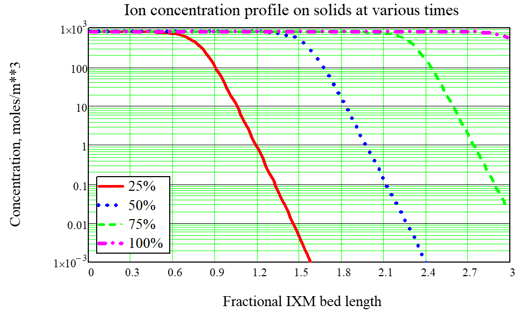
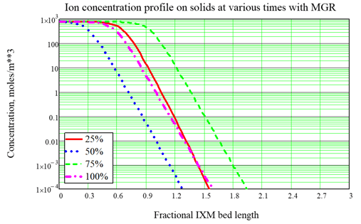
As done for Fukushima, the most typical use of the model is to optimize the service time of ion exchange modules (IXMs). A typical design for an ion exchange system includes two or three modules in series which are rotated during service. For nuclear applications we often consider three IXMs in series, with the concept that the third and last IXM is an “insurance policy.” So the strategy for IXM use is called the Merry-Go-Round (MGR) approach: The lead IXM is loaded up and changed out according to a criterion such as expected Curie loading, then the second IXM is promoted to the lead position, the last or “lag” IXM is promoted to the second position, and a new “insurance” IXM is placed in the new lag position. A key point of using the FAI IXM model is to optimize the choice of the changeout criterion, which is hard to do by Curie loading but is easy to do based upon the time of service, quantified in terms of effective number of bed volumes processed. As an example, consider a system with 3 IXMs in series, fed by a source with no changeout. The ion concentration profiles at various times during a cleanup campaign are shown in Figure 2. With no changeout, the ion loading builds up and eventually the modules allow breakthrough (input ions can leak out the back end) and eventually exhaustion (the output is nearly the same as the input, so the system is useless). When MGR changeout is performed 50% through the original simulation, breakthrough to the “insurance” IXM is prevented. In these figures, the fractional length is the distance based upon one of the IXMs in series, so that breakthrough into the lag IXM is seen by looking for significant ion concentration after position 2.0, and complete exhaustion is indicated by significant ion concentration near position 3.0. In a subsequent article we will show some important features of the updated model:
These are important for better estimate of the IXM changeout rate and the cost estimate for an IXM system. Figure 2, Example calculation without MGR changeout.
Figure 3, Example calculation with MGR changeout
For more information please contact Jim Burelbach at burelbach@fauske.com. |