Hazards Analysis, Code Compliance & Procedure Development

Services to identify process safety hazards and facilitate compliance with established standards and codes.

Combustible Dust Testing

Laboratory testing to quantify dust explosion and reactivity hazards

Flammable Gas & Vapor Testing

Laboratory testing to quantify explosion hazards for vapor and gas mixtures

Chemical Reactivity Testing

Laboratory testing to quantify reactive chemical hazards, including the possibility of material incompatibility, instability, and runaway chemical reactions

ISO Accreditation and Scope
Fauske & Associates fulfills the requirements of ISO/IEC 17025:2017 in the field of Testing
DIERS Methodology

Design emergency pressure relief systems to mitigate the consequences of unwanted chemical reactivity and account for two-phase flow using the right tools and methods

Deflagrations (Dust/Vapor/Gas)

Properly size pressure relief vents to protect your processes from dust, vapor, and gas explosions

Effluent Handling

Pressure relief sizing is just the first step and it is critical to safety handle the effluent discharge from an overpressure event

Thermal Stability

Safe storage or processing requires an understanding of the possible hazards associated with sensitivity to variations in temperature

UN-DOT

Classification of hazardous materials subject to shipping and storage regulations

Safety Data Sheets

Develop critical safety data for inclusion in SDS documents

Biological

Model transport of airborne virus aerosols to guide safe operations and ventilation upgrades

Radioactive

Model transport of contamination for source term and leak path factor analysis

Fire Analysis

Model transport of heat and smoke for fire analysis

Flammable or Toxic Gas

transport of flammable or toxic gas during a process upset

OSS consulting, adiabatic & reaction calorimetry and consulting

Onsite safety studies can help identify explosibility and chemical reaction hazards so that appropriate testing, simulations, or calculations are identified to support safe scale up

Mechanical, Piping, and Electrical

Engineering and testing to support safe plant operations and develop solutions to problems in heat transfer, fluid flow, electric power systems

Battery Safety

Testing to support safe design of batteries and electrical power backup facilities particularly to satisfy UL9540a ed.4

Hydrogen Safety

Testing and consulting on the explosion risks associated with devices and processes which use or produce hydrogen

Spent Fuel

Safety analysis for packaging, transport, and storage of spent nuclear fuel

Decommissioning, Decontamination and Remediation (DD&R)

Safety analysis to underpin decommissioning process at facilities which have produced or used radioactive nuclear materials

Laboratory Testing & Software Capabilities

Bespoke testing and modeling services to validate analysis of DD&R processes

Nuclear Overview

Our Nuclear Services Group is recognized for comprehensive evaluations to help commercial nuclear power plants operate efficiently and stay compliant.

Severe Accident Analysis and Risk Assessment

Expert analysis of possible risk and consequences from nuclear plant accidents

Thermal Hydraulics

Testing and analysis to ensure that critical equipment will operate under adverse environmental conditions

Environmental Qualification (EQ) and Equipment Survivability (ES)

Testing and analysis to ensure that critical equipment will operate under adverse environmental conditions

Laboratory Testing & Software Capabilities

Testing and modeling services to support resolution of emergent safety issues at a power plant

Adiabatic Safety Calorimeters (ARSST and VSP2)

Low thermal inertial adiabatic calorimeters specially designed to provide directly scalable data that are critical to safe process design

Other Lab Equipment and Parts for the DSC/ARC/ARSST/VSP2 Calorimeters

Products and equipment for the process safety or process development laboratory

FERST

Software for emergency relief system design to ensure safe processing of reactive chemicals, including consideration of two-phase flow and runaway chemical reactions

FATE

Facility modeling software mechanistically tracks transport of heat, gasses, vapors, and aerosols for safety analysis of multi-room facilities

Blog

Our highly experienced team keeps you up-to-date on the latest process safety developments.

Process Safety Newsletter

Stay informed with our quarterly Process Safety Newsletters sharing topical articles and practical advice.

Resources

With over 40 years of industry expertise, we have a wealth of process safety knowledge to share.

Published September 6, 2017

Non/Equilibrium Flashing Flows in Safety Relief Valves (SRVs)

Further Clarification of Non-Equilibrium and Equilibrium Flashing Flows Through Top Located Safety Relief Valves (SRVs)

By:  Hans K. Fauske, D.Sc., Regent Advisor, Fauske & Associates, LLC


Non-Equilibrium Flashing Flow

            If all liquid exist at the stagnation condition (no vapor), extensive data suggest that a simple length criterion of the order of 100 mm characterizes the residence time (~ of the order of 1 ms) requirement for approaching equilibrium flashing flows which are well described by the Equilibrium Rate Model (ERM) (Fauske, 1985)

                                                                                                                Eq 1.jpg                                                                                                                                                                     (1)

where h sysmbol-1.jpgis the latent heat of evaporation, vfg is the change in liquid-vapor specific volume, T is the temperature and C is the liquid specific heat, all evaluated at stagnation condition.  In contrast, the maximum non-equilibrium mass flux as the length approaches zero is given by

                                                                                                     Eq 2.jpg                                                                                                                                                                     (2)

where P is the stagnation gauge pressure and ρ is the liquid stagnation density.  Considering that


                                                             Gmax >> GERM                                                (3)

determines the relevant velocity and the length requirement of about 100 mm for all liquid stagnation condition (near saturated liquid and subcooling).

Equilibrium Flashing Flow

            If liquid-vapor (void fraction > 0.1) exist at the stagnation condition, the length L (mm) required to satisfy a residence time of about 1 ms is given by

                                                             L (mm) = 1 (ms) g GERM/r (mm/ms)                 (4)

resulting in a length requirement much smaller than 100 mm.  In other words 100 mm length requirement is only relevant to all liquid stagnation conditions.

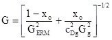
            Given the above observations, Eq. 1 can be used without modification to estimate flashing two-phase flows through top located SRVs for relief sizing purposes using the following equation (Fauske, 1999) if Eq. 4 and stagnation vapor void fraction a > 0.1 are satisfied

                                                                                                eq 5.jpg                                  (5)

where xo is the stagnation quality, CDg is the valve manufacturer certified discharge coefficient for gas flow, and Gg is the gas flow (sonic or subsonic) through an ideal nozzle.  An example of comparison with Eq. 5 and experimental data is illustrated below.  In this case Eq. 4 suggests a length L of only about 10 mm to satisfy equilibrium flashing which is clearly satisfied by the SRV.  Furthermore a stagnation quality of xo = 0.001 is equivalent to a = 0.14 at the 10.6 bar stagnation pressure.

           Steam Water Flashing Data Both requirements to satisfy equilibrium flashing flow are sensitive to the stagnation pressure.  As an example consider a stagnation pressure of 62 bar, result in L = 40 mm and xo = 0.0048, which is consistent with experimental data (Sozzi and Sutherland, 1975.)

References

Hans K. Fauske, 1985, "Flashing Flows Or: Some Practical Guidelines for Emergency Releases," Plant/Operations Progress, July, 1985.

Hans K. Fauske, 1999, "Determine Two-Phase Slows During Releases," Chemical Engineering progress, February, 1999.

Sozzi, G. L. and Sutherland, W. A., 1975, "Critical Flow of Saturated and Subcooled Water at High Pressure," Report NEDO-13418, General Electric Company, San Jose, CA (July).

For more information regarding this or other relief system design concerns, contact us at info@fauske.com, 630-323-8750

SUBSCRIBE TO OUR PROCESS SAFETY NEWS

Sign up for our newsletter to Get all the latest information

Share this article

Find more resources articles

OR
RESET