Innovative Hydrogen Removal Design For Shielded Waste Containers
By: James P. Burelbach, PhD, Director, Systems Modeling, Fauske & Associates
A key driver in safe handling of spent nuclear fuel (SNF), and in particular for damaged or degraded fuel and associated fuel-bearing waste streams (like broken fuel pieces or sludge), is the management of hydrogen to prevent the accumulation of flammable gas mixtures. Hydrogen generally evolves either from radiolysis of water or as a product of chemical reactions. Metallic uranium fuel waste, of the type found at former reprocessing sites such as Hanford (US) and Sellafield (UK), requires particular attention because the uranium metal is chemically reactive. Uranium (like other metals) reacts with available water or water vapor to form oxides and hydrogen and also generates heat. The heat of reaction must be removed, ideally by passive mechanisms, to control the temperature of the reactants and prevent an exponential increase in reaction rates. Thus, thermal stability (i.e. the potential for a runaway chemical reaction) must be accounted for when designing a safe process for handling, transport and storage of potentially chemically reactive material.
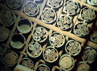
One obvious solution to prevent hydrogen evolution by either chemical reactions or radiolysis is to thoroughly dry the waste and store it in a sealed container, similar in concept to dry storage of commercial SNF. This is practical if the quantity and form of the nuclear waste is amenable to drying within an acceptable timeframe, and requires a detailed understanding of the transport phenomena associated with the drying process, in particular for porous water-bearing debris. Such a drying process was successfully implemented for 2000 tons of damaged spent fuel, fuel “scrap” and fuel particulate at the U.S. Department of Energy’s Hanford Site (Figure 1; Loscoe, 2000) and can be generalized for application to similar legacy waste at Sellafield and to Fukushima fuel debris (Plys & Epstein, 2015).

Figure 1. Severely damaged SNF and sludge before removal from Hanford K East Basin (www.feandc.com)
Some waste streams which do not lend themselves to drying include sludge (formed by corrosion and deterioration of stored fuel and other accumulated waste), cemented (grouted) containers of fuel pieces, and containers with spent zeolite or other ion exchange materials. Even though spent ion exchange media do not contain uranium, accumulated fission products such as cesium and strontium cause radiolysis of the water in the media pore space and in pore space within media particles. It can be difficult to remove water from the internal pores within zeolites, for example. Thus, there is a need to provide vented containers for interim storage of such waste.
Thick-walled steel containers are convenient for this application because they provide radiation shielding, and their design is relatively simple. Self-shielded boxes are being considered for use at Sellafield, where there is a recognized urgency to remove a large amount of fuel-bearing waste from the present unfavorable storage locations. Self-shielded boxes also offer a way to accelerate removal of fuel pieces and scrap, providing a path to interim storage ahead of development of a drying or encapsulation facility. Since the boxes themselves are shielded, the design of the box storage facility is greatly simplified.
The Sellafield waste materials, and eventually debris from Fukushima, may be stored in shielded boxes with filtered vents to allow removal of hydrogen and prevent formation of flammable gas mixtures in the box. However, unlike thin-walled containers, the shielded boxes (with wall thickness of about 30 cm) require that gas flow channels or “boreholes” be drilled through the wall or lid. The boreholes provide a path for hydrogen from the box interior to get to the filters, which would be mounted on the exterior of the box where they are accessible for maintenance and inspection. The required number of filters depends on the type and quantity of waste that is stored in the box. Boreholes drilled through thick shielding naturally increase the resistance to hydrogen removal, and thus reduce the effectiveness (efficiency) of a given filter assembly. There are practical limits to the number of filters that can be installed on a box (e.g., cost, structural integrity), so it is important that the filters and boreholes be configured to function as efficiently as possible.
Innovative Solution for Hydrogen Removal
The innovative work described here was performed by Fauske & Associates, a wholly owned subsidiary of Westinghouse Electric Company, LLC, in cooperation with Sellafield, Ltd. In partnership, we have conceived, modeled, and experimentally verified an effective method for hydrogen removal from shielded boxes with significant hydrogen generation rates. This innovation minimizes the number of filters required for passive storage of spent metallic nuclear fuel pieces and other hydrogen-generating waste streams.
Many commercially available filters are suitable for removal of hydrogen from unshielded nuclear waste containers such as 200 L drums. The rate of hydrogen removal through a filter varies with filter size and materials. The key filter specification provided by the manufacturer is the filter coefficient, expressed in units of moles hydrogen per second per mole fraction difference across the filter. Typical values range from 10-5 to over 2 x 10⁻⁴ moles/s/mole fraction. The size (and quantity) of filters for a given application is chosen based on the limiting hydrogen source rate and the required safe upper limit for hydrogen concentration, usually taken to be either the lower flammability limit (LFL, 4% hydrogen in air) or 25% of the LFL (i.e. 1% hydrogen in air).
Shielded containers are made of much thicker materials than conventional containers. In order for the hydrogen to escape from the container, it must first pass through a borehole drilled through the shielding material (the flow path) then diffuse through the filter and out into the surrounding atmosphere. The rate at which hydrogen escapes from the container depends upon the difference in hydrogen concentration between the two sides of the filter, which in turn depends on the effectiveness of hydrogen transport through the borehole. In other words, because shielding keeps the bulk of the hydrogen in the waste container, away from the filter, the effective hydrogen flow rate through the filter is reduced, so the flow of hydrogen through any filter is less effective in a shielded container than it would be for the same filter on an unshielded container. The situation is further complicated by the simultaneous flow of other gases (e.g. oxygen, nitrogen, etc.) which can also move in or out through the filter, depending on the driving concentration differences for those species. For systems where the hydrogen source is chemical reactions, the hydrogen source rate is typically much larger than that from radiolysis, and this can make hydrogen removal even more challenging.
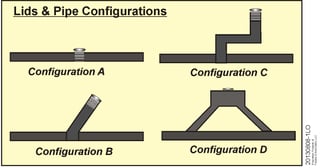
Figure 2 illustrates different filter configurations which have been analyzed first by modeling and then validated by experiments (represented conceptually by different arrangements of pipes and filters on a vessel lid). Configuration A (direct mounted filter) was tested in order to verify the manufacturer’s stated filter performance for different types of commercial filters (actual performance was generally better than stated on the filter spec sheet). Both small scale tests (a single filter on a smaller vessel) and large scale testing (up to 8 filters on a full scale box “lid”) were performed. At first the tests were performed transiently by establishing an initial hydrogen concentration of about 4% and then allowing the concentration to decay as hydrogen was vented and replaced by air coming in the filter. Later tests incorporated a steady-state methodology in which a constant hydrogen source rate (consistent with anticipated waste package conditions) was established.

Figure 2. Various borehole and filter configurations analyzed by modeling and experiments
Modeling and experiments revealed the limitation of a single borehole approach. It was found, for example, that a shielded container with a single borehole of 20 mm diameter and 300 mm length drilled through the shielding (e.g. Configuration B) would allow hydrogen to escape at only one-tenth the rate that it would in an unshielded container (Configuration A). In other words, the system efficiency for a single borehole is only about 10%, and as a consequence the number of filters required would increase tenfold relative to a thin-walled container.
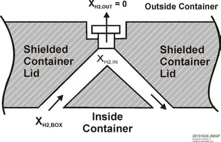
On the other hand, the dual borehole arrangement (Configuration D) promotes hydrogen transport to the filter. The hydrogen concentration in a plenum immediately beneath the filter (XH2,IN, see Figure 3) is lower than the hydrogen concentration in the shielded container or box (XH2,BOX) so the density difference induces circulation. Thus, hydrogen-bearing gas from the shielded container circulates up one of the boreholes into the plenum beneath the filter and then down the other borehole, returning to the container. Diffusion through the filter is driven by the hydrogen mole fraction difference, XH2,IN - XH2,OUT. The study demonstrated that Configuration D is nearly as effective as Configuration A, providing an innovative solution to hydrogen removal from a shielded waste container.

Figure 3. Dual borehole design with a single filter
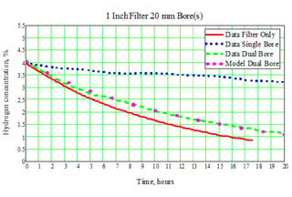
The expected performance of the dual borehole design was confirmed through experiments for different filter types, bore diameters, and variation in hydrogen concentration. An example comparison of a priori expectation versus actual system data is shown in Figure 4, which shows transient venting results for a container initially containing 4% hydrogen. The most effective venting occurs for the filter alone (no borehole), where in this example the hydrogen concentration drops below 1% within 16 hr. In comparison, the single bore design only reduces the hydrogen concentration to about 3.4% over 16 hr. The dual borehole design is much better, reducing they hydrogen to less than 1.5% within 16 hr. The efficiency of the dual bore system can be in the range of 80% to 90% (based on the measured “system” coefficient versus the “filter” coefficient), depending on the geometry and the hydrogen concentration in the shielded container. Thus, with the dual-bore design the number of filters required for a given waste package application is largely unaffected by the flow resistance due to the shielding.

Figure 4. Example experimental results and model predictions
Summary
The key to hydrogen removal from a shielded nuclear waste container is to reduce the flow resistance in the boreholes such that the filter is the dominant resistance. We have developed an innovative arrangement to promote hydrogen flow to the filter via a pair of boreholes in the shielded container lid. This design takes advantage of buoyancy-induced natural circulation. Gas from the container flows up one of the boreholes into the plenum beneath the filter and then down the other borehole, returning to the container. We have performed modeling for this design which demonstrates that the efficiency of the dual bore system can be in the range of 80% to 90%. This high efficiency minimizes the number of vents required on a shielded waste container and maximizes the quantity of waste that can be placed in a given vented container.
References
Loscoe, P. G., “Transitioning Metallic Uranium Spent Nuclear Fuel from Wet to Dry Storage,” Waste Management Conference, 2000, Tucson, Arizona
Plys, M. G., and Epstein, M., “Residual Water during Drying of Damaged Spent Nuclear Fuel and Debris,” Global 2015, Conference on the Nuclear Fuel Cycle, Paris, September 2015
We invite discussion, or feedback. For more information, please contact Jim Burelbach at burlebach@fauske.com, 630-887-5221 www.Fauske.com
#nuclear plant

