By Elizabeth Raines, Chemical Engineer, Fauske & Associates
If something is not working properly after setting up your Advanced Reactive System Screen Tool (ARSSTTM) unit (e.g. the data is noisy and is collecting erroneous data not useful in emergency relief system design, the test cell isn’t heating up during a test, the temperature doesn’t appear to be reading properly, etc.) here are some quick things to check to help eliminate the problem:
- Have you verified that all the consumable parts are in good working condition?
- Is the containment vessel and thermocouple properly grounded?
- Is the ARSST control box and heater turned on?
- Is a fuse blown in the back of the ARSST control box (this may be a problem if when you turn on the box you don’t hear the fan kick on)?
- Are the cables (thermocouple cable, heater cable, and pressure cable) separated from each other?
- Have you verified that the voltage through the heater cable is what it should be?
This article and video focus on item 1 above; verify that all consumables are working and replace them if they are questionable.
Remember, the best practice is to perform the checks above BEFORE you begin running a test.
For the ARSST, there are four primary consumable parts that benefit from electrical checks prior to testing: the thermocouple, the heater, and their respective glands. Note, in the following pictures, the locations where the multimeter leads should make contact are identified by blue and red dots, respectively.
Thermocouple
There are two primary checks to be performed to ensure your thermocouple is in good working condition:
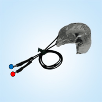
A. Verify that the resistance across the thermocouple is 3-6 ohms (for a stainless steel thermocouple)
- Turn your multimeter on and set to read resistance (might be shown with the Greek letter omega, Ω, or the word “ohms”)
- Connect one of the leads from the multimeter onto each side of the thermocouple prongs: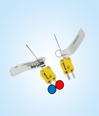
- The resistance across these two locations should read the specified resistance in ohms (note the resistance is thermocouple specific and varies based on material and length)
B. Verify that the thermocouple is not shorted out by checking that the resistance is > 10 Mega ohms
- Turn your multimeter on and set to read resistance
- Connect one of the leads from the multimeter to one of the thermocouple prongs and the other lead to the end of the thermocouple:
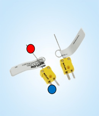
- The resistance across these two locations should read a very large resistance indicating that the thermocouple is not shorted out
Thermocouple Gland
There are two primary checks to be performed to ensure your thermocouple gland is in good working condition:
A. Plug the thermocouple into the thermocouple gland. Verify that the resistance across the thermocouple gland is 3-6 ohms (for a stainless steel thermocouple)
- Turn your multimeter on and set to read resistance
- Connect each of the leads from the multimeter onto each side of the thermocouple gland prongs:
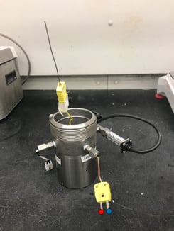
- The resistance across these two locations should read the specified resistance in ohms for the thermocouple
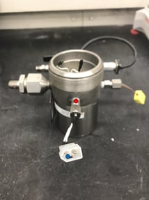
B. Verify that the thermocouple is not shorted out to the vessel and that the resistance is > 10 Mega ohms
- Turn your multimeter on and set to read resistance
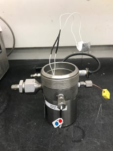
- Connect one of the leads from the multimeter to one side of the thermocouple gland prong and the other lead somewhere on the vessel:
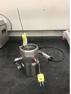 - The resistance across these two locations should read a very large resistance indicating that the thermocouple is not shorted out through the vessel
Heater
There are two primary checks to be performed to ensure your heater is in good working condition:
A. Verify that the resistance across the heater is 23.5-24.5 ohms
- Turn your multimeter on and set to read resistance
- Connect each of the leads from the multimeter onto each prong of the heater
B. Verify that the heater is not shorted out and that the resistance is > 10 Mega ohms
- Turn your multimeter on and set to read resistance
- Connect one of the leads from the multimeter to one of the heater wire prongs and the other lead to the foil part of the heater.
- The resistance across these two locations should read a very large resistance indicating that the heater is not shorted to the foil (>10 Mega ohms)
Heater Gland
There are four primary checks to be performed to ensure your heater gland is in good working condition: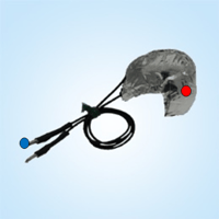
A. Verify the heater gland continuity through the vessel
- Turn your multimeter on and set to read continuity (it might look this this symbol ![]() , otherwise set to resistance)
, otherwise set to resistance)
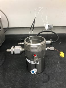
- Connect one of the multimeter leads into one of the female heater gland locations (on the interior side of the vessel) and connect the other lead to the male prong on the exterior side of the vessel (touch the metal part on each side):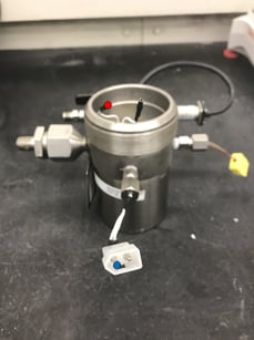
- When a complete path is reached, the multimeter will beep (and show a resistance of ~0.3-0.5 ohms). Only one pair of male/female parts should be detected as a complete path
- Swap pairs and test that the other wire is intact
B. Verify the heater gland wires are not shorted to the vessel and that the resistance > 10 Mega ohms
- Turn your multimeter on and set to read resistance
- Connect one of the multimeter leads onto one of the male heater gland prongs and connect the other lead to the vessel:
- The resistance across these two locations should read a very large resistance indicating that the heater gland is not shorted to the vessel
- Repeat and test the other prong
C. Plug the heater into the heater gland and verify that the resistance across the heater gland is 23.5-24.5 ohms
- Turn your multimeter on and set to read resistance
- Connect each of the leads from the multimeter onto each side of the prongs on the heater gland exterior:
- With the heater plugged in, the resistance across these two locations should read approximately 23.5 ohms
D. Plug the heater into the heater gland and verify that the heater and gland is not shorted out to the vessel and that the resistance is > 10 Mega ohms
- Turn your multimeter on and set to read resistance
- Connect one of the multimeter leads onto one of the male heater gland prongs and connect the other lead to the vessel:
- The resistance across these two locations should read a very large resistance indicating that the heater gland is not shorted to the vessel
- Repeat and test the other prong
If you enjoyed learning about ARSST, check out our case study on low thermal inertia adiabatic calorimetry. In this case study, FAI performs tests to determine what is the self accelerating decomposition temperature of a 50 kg package of azodicarbonamide. Download the case study now to to learn more about AKTS software, self accelerating decomposition temperature, the United States SADT test, and much more.